Electronic element pin insulating sleeve sheathing machine

A technology for insulating sleeves and electronic components, applied in auxiliary devices, metal processing, metal processing equipment, etc., can solve problems such as difficult processing, mass production, and implementation, and achieve easy processing, improved labor efficiency and The effect of insulation quality and ease of mass production

Inactive Publication Date: 2015-05-20
东兴市鸿生实业有限公司
View PDF6 Cites 5 Cited by
  • Summary
  • Abstract
  • Description
  • Claims
  • Application Information

AI Technical Summary

Problems solved by technology

Both of the above two methods use insulation methods to insulate the pins of electronic components, but they are not easy to implement, process, or mass produce.

Method used


Image

  • Electronic element pin insulating sleeve sheathing machine
  • Electronic element pin insulating sleeve sheathing machine
  • Electronic element pin insulating sleeve sheathing machine

Examples


Embodiment 1

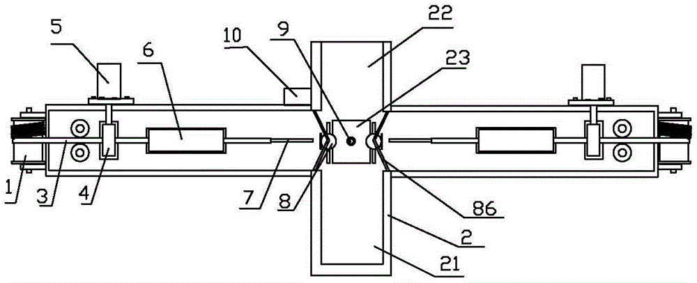
[0027] figure 1 , figure 2 , image 3 , Figure 4 , Figure 5 A schematic diagram of the structure of an insulating sleeve fitting machine is given when the left and right sides of an electronic component are a circular pin. refer to figure 1 , figure 2 , image 3 , Figure 4 , Figure 5 Make the invention. The electronic component pin insulating sleeve fitting machine includes an insulating sleeve roll 1 and a "ten"-shaped workbench 2, and an insulating sleeve 3 is wound on the insulating sleeve roll 1, which is characterized in that: There are two insulating sleeve rolls 1 on the left and right, which are symmetrically fixed on the outside of the left and right ends of the "ten"-shaped workbench 2 through brackets; Tube conveying nip roller 4, one end of the shaft of the insulating casing conveying nip roller 4 at the left and right ends is respectively connected with the main shaft of the corresponding micro-stepping motor 5, and the stepping rotation of the two...

Embodiment 2

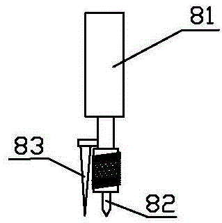
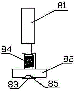
[0038] Image 6 , Figure 7 , Figure 8 The side view of the insulating sleeve cutting device, the axial section of the magnetic sleeve and the suspended iron bar, and the enlarged side view of the insulating sleeve conveying nip roller are given when the left and right sides of an electronic component are multiple flat pins.

[0039] combine figure 1 , figure 2 , when there are multiple flat pins on the left and right sides of the electronic component, the insulating sleeve cutting device, the magnetic sleeve and the suspended iron bar and the insulating sleeve conveying nip roller are as follows: Image 6 , Figure 7 , Figure 8 shown. Image 6 The center cut arc opening 85 is a partial opening, and the width of the flat opening is consistent with the width of multiple flat pins of the electronic component; the axial section of the magnetic sleeve and the suspension iron bar is as follows: Figure 7 As shown, the magnetic sleeve 6 and the suspension iron bar 7 are fl...


PUM


Abstract

The invention discloses an electronic element pin insulating sleeve sheathing machine, which comprises insulating sleeve winding-up rollers and a cross-shaped operating platform, wherein the insulating sleeve winding-up rollers are wound with insulating sleeves, the electronic element pin insulating sleeve sheathing machine is characterized in that the left and right insulating sleeve winding-up rollers are respectively symmetrically fixedly arranged on the outer sides of the left end and the right end of the cross-shaped operating platform through a bracket; an insulating sleeve conveying clamp roller, a magnetic jacket, a suspension iron strip and an insulating sleeve cutting device are sequentially arranged on each of the left side and the right side of a rectangular operating platform; shaft ends of the two insulating sleeve winding-up rollers are connected with a minitype stepping motor respectively; the suspension iron strip penetrates through each insulating sleeve, and the end of the suspension iron strip props against the end of each electronic element pin. According to the electronic element pin insulating sleeve sheathing machine, not only can the electronic element pin is sheathed with the insulating sleeve, but also implementation is fast, processing is easy and batch production is easy, the insulating sleeves can simultaneously sheath the electronic element pins at the two sides simultaneously, and can be subjected to hot cutting and cold cutting, and simultaneously, the labor efficiency and insulating quality can be greatly increased.

Description

technical field [0001] The invention relates to an improvement of an electronic component pin insulation method, in particular to an electronic component pin insulating sleeve fitting machine. Background technique [0002] The electronic components in the circuit diagram are realized by welding the pins of the electronic components on the printed board. Because the pins of the electronic components are sometimes close together, it is very easy to produce a short circuit under harsh conditions. In the case of electromagnetic pulses, there will be cause momentary disruption. Therefore, it is very necessary to insulate the pins of electronic components. [0003] At present, there are usually no insulation measures for soldering the pins of electronic components on the printed board, especially for chips with dense pins, it is difficult to implement interval insulation on the pins, so short-circuit accidents between the pins are difficult to avoid, such as Currently used compu...

Claims


Application Information

Patent Timeline
Patent Type & Authority Applications(China)
IPC IPC(8): B29C63/18B26D1/04B26D7/10B23K3/08
Inventor 高旭国
Owner 东兴市鸿生实业有限公司
Why Eureka
Try Eureka