Bicycle automatic shock absorber system for
A bicycle and shock absorber technology, which is applied to bicycle accessories, shock absorbers, springs/shock absorbers, etc., can solve the problems of uncomfortable riding, different bicycles and four-wheeled vehicles, and poor stability, so as to improve pedaling efficiency Effect
- Summary
- Abstract
- Description
- Claims
- Application Information
AI Technical Summary
Problems solved by technology
Method used
Image
Examples
no. 1 example
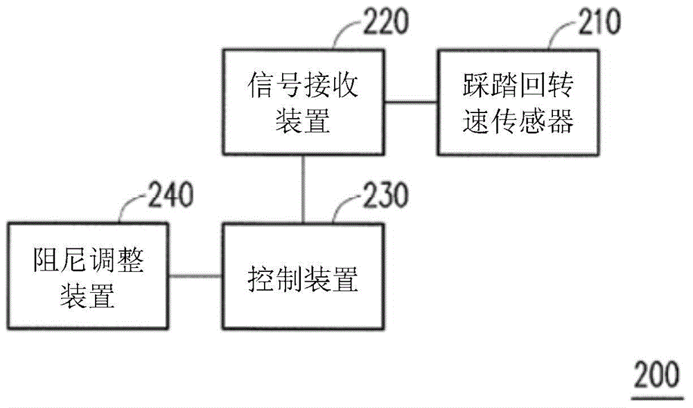
[0110] figure 2 is a block diagram of the bicycle automatic control shock absorber system according to the first embodiment of the present invention. In this embodiment, the bicycle automatic control shock absorber system 200 includes a pedaling speed sensor 210 , a signal receiving device 220 , a control processing device 230 and a damping adjustment device 240 .
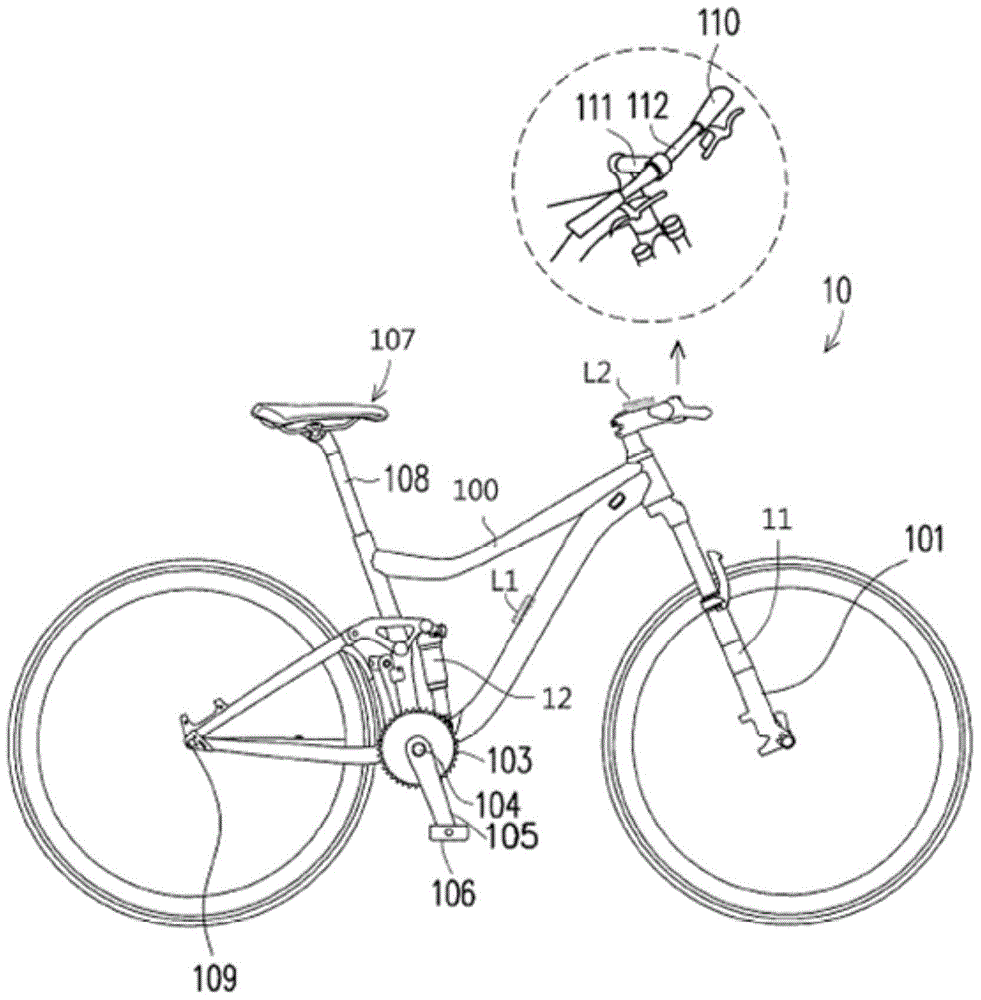
[0111] The pedaling rotation speed sensor 210 is used to detect the pedaling rotation speed of the bicycle 10 and output a pedaling signal. The pedaling rotation speed sensor 210 can be installed at one of the chainring 103 , the crank shaft 104 , the crank 105 , the pedal 106 , and the frame 100 of the bicycle 10 . In addition, the pedaling speed sensor 210 can also be worn on the legs of the rider of the bicycle 10 , such as the legs (inner thighs) or shoes.
[0112] The signal receiving device 220 is coupled to the pedaling rotation speed sensor 210 and the control processing device 230 to receive the pedalin...
no. 2 example
[0123] Figure 4A and Figure 4B is a block diagram of the bicycle automatic control shock absorber system according to the second embodiment of the present invention. exist Figure 4A Among them, the bicycle automatic control shock absorber system 400 includes a posture sensor 410 , a signal receiving device 220 , a control processing device 230 and a damping adjustment device 240 . Here, components having the same functions as those in the first embodiment are assigned the same symbols, and related descriptions are omitted.
[0124] The posture sensor 410 is used to detect whether the posture adopted by the rider riding the bicycle 10 is a sitting posture or a standing posture, and outputs a posture signal. The signal receiving device 220 is coupled to the gesture sensor 410 to receive gesture signals. The control processing device 230 is coupled to the signal receiving device 220 , and outputs a level control signal to the damping adjustment device 240 according to the ...
no. 3 example
[0136] Figure 6 is a block diagram of the bicycle automatic control shock absorber system according to the third embodiment of the present invention. The bicycle automatic control shock absorber system of this embodiment includes a pedaling speed sensor and a gradient sensor. Please refer to Figure 6 , the bicycle automatic control shock absorber system 600 includes a pedaling speed sensor 210 , a gradient sensor 610 , a signal receiving device 220 , a control processing device 230 and a damping adjustment device 240 . Here, components having the same functions as those in the first embodiment are assigned the same symbols, and related descriptions are omitted.
[0137] The slope sensor 610 is used to detect the slope of the current location of the bicycle 10 and output a slope signal, and the slope signal is transmitted to the control processing device 230 through the signal receiving device 220 . Here, the control processing device 230 determines the damping curve relat...
PUM
 Abstract
Description
Claims
Application Information
 - R&D
- Intellectual Property
- Life Sciences
- Materials
- Tech Scout
- Unparalleled Data Quality
- Higher Quality Content
- 60% Fewer Hallucinations
Browse by: Latest US Patents, China's latest patents, Technical Efficacy Thesaurus, Application Domain, Technology Topic, Popular Technical Reports.
© 2025 PatSnap. All rights reserved.Legal|Privacy policy|Modern Slavery Act Transparency Statement|Sitemap|About US| Contact US: help@patsnap.com


