

Mask plate and preparation method thereof
A mask plate and buffer hole technology, applied in the field of mask plate and its preparation, can solve problems such as tension deformation, and achieve the effects of reducing tension deformation, improving evaporation effect, and ensuring accuracy
- Summary
- Abstract
- Description
- Claims
- Application Information
AI Technical Summary
Problems solved by technology
Method used
Image

Examples
Embodiment 1
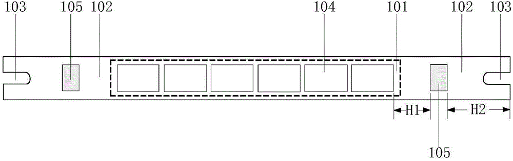
[0031] In the process of making an OLED display, organic materials need to be vapor-deposited on the surface of a glass substrate, and a mask plate is required in the process of evaporating organic materials to obtain a desired pattern on a glass substrate. figure 1 It is a schematic structural diagram of a mask plate provided by Embodiment 1 of the present invention. Such as figure 1 As shown, the mask includes a mask body, the mask body includes a graphic area 101 and a blank area 102, and the blank area 102 is arranged on the periphery of the graphic area 101, so that the blank area 102 surrounding the graphic area 101 . In this embodiment, the mask is a strip mask, so the blank area 102 is disposed at both ends of the strip mask. Both ends of the strip-shaped mask are also provided with U-shaped fixing grooves 103, through which the strip-shaped mask is fixed to the mask frame.
[0032] In this embodiment, the graphics area 101 is provided with vapor deposition holes 10...
Embodiment 2
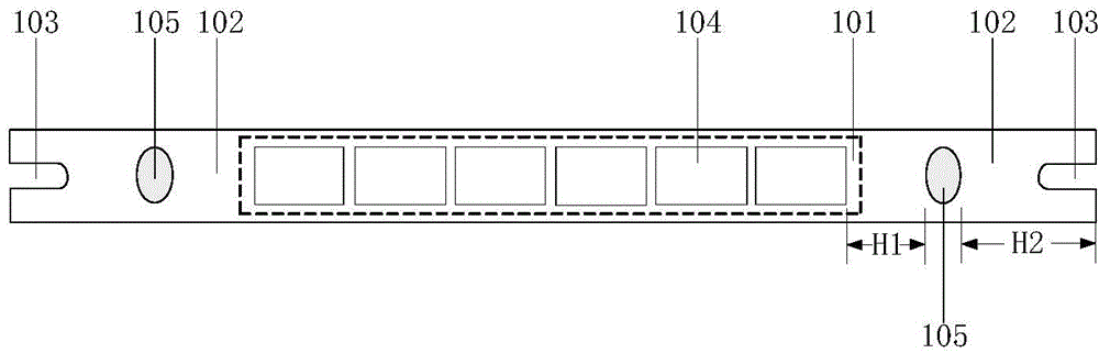
[0039] figure 2 It is a schematic structural diagram of a mask plate provided by Embodiment 2 of the present invention. Such as figure 2 As shown, the mask includes a mask body, the mask body includes a graphic area 101 and a blank area 102, and the blank area 102 is arranged on the periphery of the graphic area 101, so that the blank area 102 surrounding the graphic area 101 . The graphics area 101 is provided with evaporation holes 104, and the blank area 102 is provided with buffer holes 105, the buffer holes 105 are set corresponding to the evaporation holes 104, and the main function of the buffer holes 105 is to stretch the net. The tension is redundant to disperse the influence of the net tension on the vapor deposition holes 104, thereby eliminating or reducing the tension deformation of the mask plate due to the tension of the net, improving the evaporation effect, and improving the accuracy of the subsequent evaporation process. Provide strong protection.
[00...
Embodiment 3
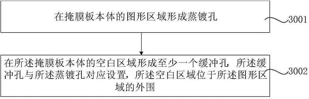
[0044] image 3 It is a flowchart of a method for preparing a mask plate provided by Embodiment 3 of the present invention. Such as image 3 Shown, described preparation method comprises:
[0045] Step 3001, forming evaporation holes in the pattern area of the mask body.
[0046] Step 3002, forming at least one buffer hole in a blank area of the mask body, the buffer hole is set corresponding to the evaporation hole, and the blank area is located at the periphery of the pattern area.
[0047] In this embodiment, at least one row of vapor deposition holes is formed laterally in the pattern area of the mask body, and the mask plate forming the vapor deposition holes is preheated in an environment of 110° C. Apply photoresist. After the exposure treatment, a required buffer hole pattern is formed in the blank area of the mask, and the mask is annealed in an environment of 135° C. The mask plate is developed using NaOH solution, and finally at least one buffer hole is...
PUM
| Property | Measurement | Unit |
|---|---|---|
| eccentricity | aaaaa | aaaaa |
Abstract
Description
Claims
Application Information