Rotating evaporator with process-dependent rotating speed regulation

a technology of rotating speed regulation and rotating evaporator, which is applied in the direction of separation processes, instruments, specific gravity measurement, etc., can solve the problems of limited efficiency or evaporation capacity of rotary evaporators, and achieve the effect of increasing the evaporation surface of medium

Inactive Publication Date: 2006-12-26
GENSER HANS GEORG
View PDF13 Cites 15 Cited by
  • Summary
  • Abstract
  • Description
  • Claims
  • Application Information

AI Technical Summary

Benefits of technology

[0019]The invention is based on the further consideration of automatically controlling or regulating the rotating speed of the rotating container and making this control or regulation of the rotating speed of the rotating container dependent on at least one other indirectly or directly detected process value for the evaporation process. In this way, changes or excessive deviations of the current process conditions or process values can be at least partially prevented or balanced out by a corresponding adjustment of the rotating speed of the rotating container.
[0020]By appropriately setting or adjusting the rotating speed of the rotating container, a film (or layer) of the medium is generated at least on a portion of the inner wall of the rotating container. In this way, the evaporation surface of the medium is considerably increased. The film of the medium should be as uniform as possible over the inner surface of the rotating container, in connection with which it is especially advantageous if the film is as coherent as possible and the largest possible surface of the inner wall of the rotating container is covered or wetted. The evaporation capacity (or evaporation rate) of the rotary evaporator can thus be set as high as possible or optimized by control or regulation of the rotating speed of the rotating container.
[0021]There will be a higher level of the medium in the lower area of the rotating container, at least during a predominant period of the evaporation process, that is, there will be a larger portion of the medium drawn downward by the force of gravity as a reservoir, from which the film of the medium is formed on the inner surface of the rotating container due to the rotation at adapted rotating speed and the resulting pulling and centrifugal forces. At each passage of the inner wall of the rotating container through this reservoir of the medium, the inner wall pulls adhering medium along, which forms into a film over the inner wall of the rotating container. During the rotation of the rotating container, the substance or substances then evaporates or evaporate from the film and when the reservoir is reached, the film is at least partially renewed or regenerated again. This constant renewal of the film of the medium prevents the forming of a stationary concentration precipitation inside the film along its thickness from the inside to the outside (radial concerned gradient) and thereby the forming on the film surface of a “crust” or “skin” of non-evaporated residual substance or low-solvent residual medium hindering the evaporation process. In addition, the formation of a stationary film on the inner wall of the rotating container is also prevented.

Problems solved by technology

For this reason, the efficiency or the evaporation capacity of this rotary evaporator is limited.

Method used


Image

  • Rotating evaporator with process-dependent rotating speed regulation
  • Rotating evaporator with process-dependent rotating speed regulation
  • Rotating evaporator with process-dependent rotating speed regulation

Examples


Embodiment Construction

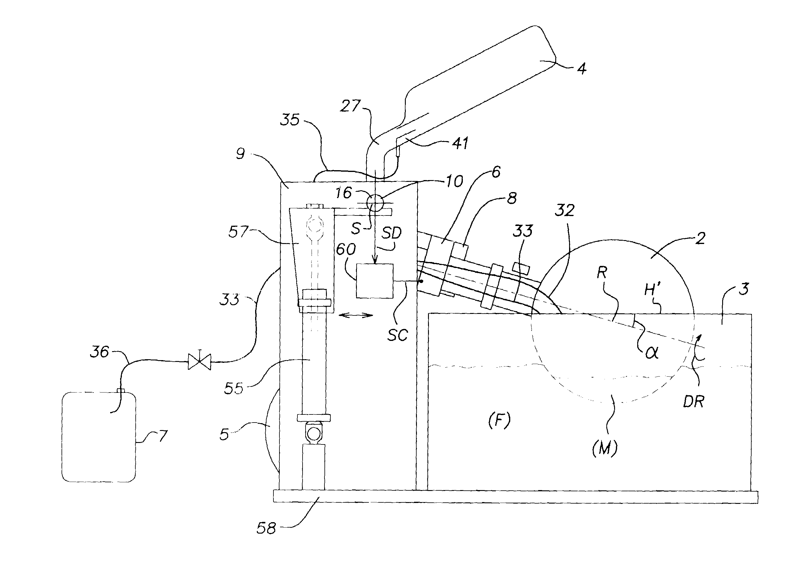
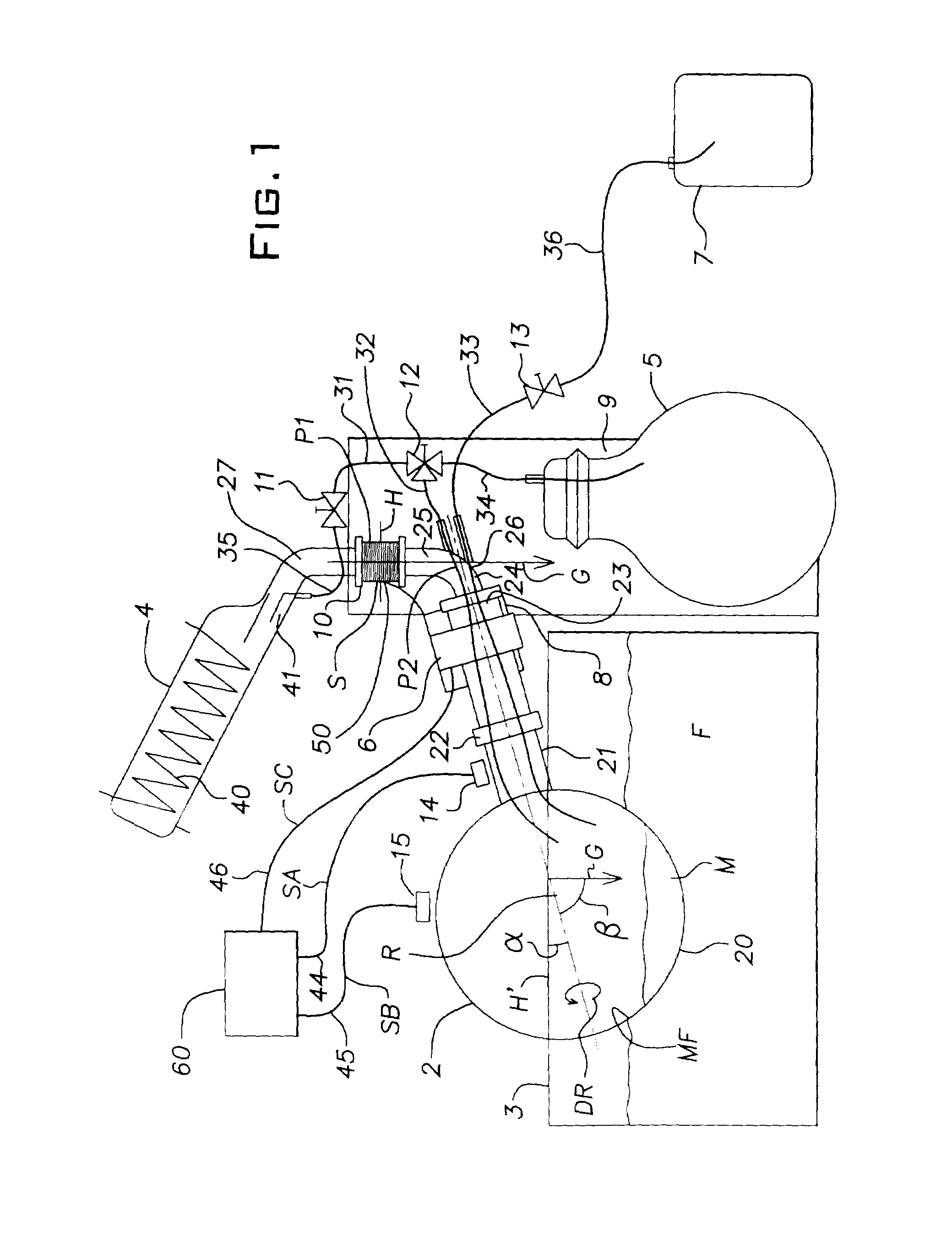
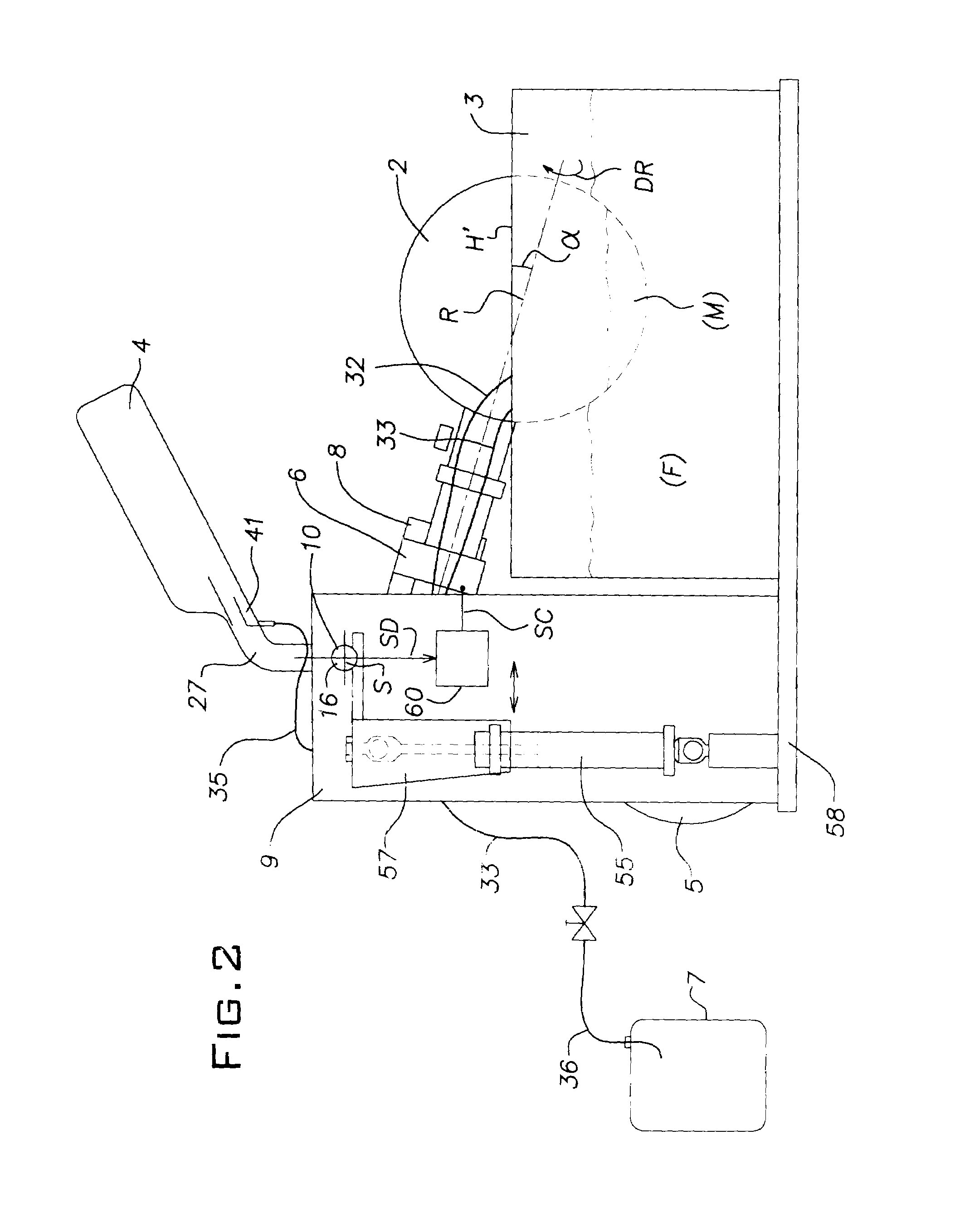
[0065]The rotary evaporators according to FIG. 1 and FIG. 2 each comprise a rotating container (or: work vessel, rotating flask) 2 that can be rotated (turned) around an axis of rotation (turning axis) R via a drive means 6. The rotating container 2 dips into a liquid bath 3 with a liquid f. The liquid F. serves as heat transfer medium and can consist of water or, especially at higher temperatures, also of mineral or silicon oil or also of glycol. The inclination of the axis of rotation R relative to the horizontal H′ oriented orthogonally relative to gravity (gravitational force) G is characterized by an angle α and the inclination of the axis of rotation R relative to the vertical oriented parallel to gravity is characterized by an angle β, where α+β=90° and β≠90°.

[0066]At the opposite end of the drive means 6, a receiving device (connecting sleeve, hollow shaft) 23 is arranged that is stationary, that is, cannot be rotated at the same time, and surrounds and holds a line 26 to co...


PUM

PropertyMeasurementUnit
acute angleaaaaaaaaaa
gravityaaaaaaaaaa

Abstract

In a rotary evaporator, the rotating speed of the rotating flask is automatically controlled or regulated dependent upon a detected process value, particularly the vibration behavior or the mass moment of inertia of the rotating flask.

Description

BACKGROUND OF THE INVENTION[0001]The invention relates to a device and a process for evaporating at least one substance.[0002]Devices referred to as rotary evaporators are known, for evaporating substances, particularly for evaporating solvents when concentrating or distilling pharmaceutical or chemical products. With these rotary evaporators, the liquid substances to be evaporated are placed into the cavity of a rotating flask (evaporation vessel) generally rotatable in a heating bath. By rotating the flask, a thin liquid film is generated on the inside of the rotating flask, from which the substances, particularly the solvent, evaporate. A certain portion of the substance or the solvent also evaporates directly from the surface of the liquid in the rotating flask. The vapor is conveyed from the rotating flask via a vapor line to a condenser where it condenses out again. In general, a negative pressure or vacuum is also generated in the rotating flask in order to increase the vapor...

Claims


Application Information

Patent Timeline
Patent Type & Authority Patents(United States)
IPC IPC(8): B01D3/08B01D3/42
CPCB01D3/085B01D3/42
Inventor GENSER, HANS GEORG
Owner GENSER HANS GEORG
Why Eureka
Try Eureka