Partitioned-pulping efficient pulper

A pulper and zonal technology, which is applied in raw material separation, textile and papermaking, fiber raw material processing, etc., can solve the problems of low pulping efficiency, high energy consumption, insufficient pulping area, etc.

Inactive Publication Date: 2015-05-20
UNIV OF JINAN
View PDF6 Cites 5 Cited by
  • Summary
  • Abstract
  • Description
  • Claims
  • Application Information

AI Technical Summary

Problems solved by technology

[0004] Aiming at the problems of insufficient pulping area, uneven particles, low pulping efficiency and high energy consumption in the existing pulper, the present invention provides a high-efficiency pulping system for zoned pulping that can effectively solve the above problems. pulp machine

Method used


Image

  • Partitioned-pulping efficient pulper
  • Partitioned-pulping efficient pulper
  • Partitioned-pulping efficient pulper

Examples


Embodiment

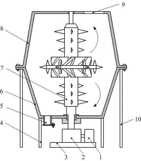
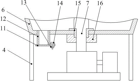
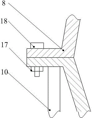
[0026] Such as figure 1 , figure 2 , image 3 with Figure 4 As shown, the high-efficiency pulper for partitioned pulping of the present invention is mainly composed of a shell structure, a supporting device, a power device and a pulping device. The shell structure is mainly composed of a lower tank body 6 and an upper tank body 8. The lower tank body 6 and the upper tank body 8 are fixed by a tank bolt 17 and a tank nut 18. The upper tank body 8 is provided with a feed port 9 and the lower tank body A discharge port 5 is opened on the tank body 6. The discharge port 5 is equipped with a discharge port outer barrel 12 and a discharge port bottom plate 11, and they are fixed by a discharge port bolt 13 and a discharge port nut 14. The supporting device is mainly composed of an inner support 4 and an outer support 10. The inner support 4 is mounted on the outer edge of the bottom end of the lower tank 6, and the outer support 10 is mounted on the outer edge of the connection betw...


PUM


Abstract

The invention provides a partitioned-pulping efficient pulper which mainly comprises a shell structure, a support device, a power device and a pulping device. The partitioned-pulping efficient pulper is characterized in that the pulper is divided into an upper pulping area, a middle pulping area and a lower pulping area by a regular cone frustum shaped upper tank, a lower inverted cone frustum shaped lower tank and a special rotor. Pulping of size in spiral uprising accelerated eddy flow in the upper half area is realized through a special-rotor upper-end paddle wheel, the upper tank and special-rotor upper-end large, medium and small conical teeth, pulping of the size in the middle area is realized through a special-rotor middle seat and special-rotor middle seat conical teeth, and pulping of the size in spiral descent accelerated eddy flow in the lower half area is realized through a special-rotor lower-end paddle wheel, the lower tank and special-rotor lower-end large, medium and small conical teeth.

Description

Technical field [0001] The invention relates to a partitioned type pulping high-efficiency pulper, in particular to a special rotor upper end paddle wheel, an upper tank body and a special rotor upper end large, medium and small bevel teeth to realize the spiral upward acceleration of the slurry in the upper half area. Flow pulping, the pulping of the slurry in the middle area is realized by the special rotor center seat and the special rotor center seat bevel teeth, and the lower half area is realized by the special rotor lower end blade, upper tank and special rotor lower end large, medium and small bevel teeth The spiral drop of the slurry accelerates the swirling pulping, which belongs to the technical research and development field of the pulper. Background technique [0002] The pulper makes a uniform suspension of the scraps in the water through the movement of the rotor. The uniformity and particle size of the pulp directly affect the quality of the finished paper. Theref...

Claims


Application Information

Patent Timeline
Patent Type & Authority Applications(China)
IPC IPC(8): D21B1/34
CPCD21B1/345
Inventor 安延涛赵东刘鲁宁杨玉娥赵智强宋豪
Owner UNIV OF JINAN
Why Eureka
Try Eureka