Oil transfer pump oil return structure

A technology of oil delivery pump and oil return pipe, which is applied in the field of oil return structure of oil delivery pump, can solve the problems of large energy loss, low oil return efficiency, poor drainage effect, etc., and achieve the goal of improving utilization rate, increasing oil return efficiency and avoiding energy loss Effect

Inactive Publication Date: 2015-05-20
ANHUI JIANGHUAI AUTOMOBILE GRP CORP LTD
View PDF8 Cites 0 Cited by
  • Summary
  • Abstract
  • Description
  • Claims
  • Application Information

AI Technical Summary

Problems solved by technology

[0004] Due to the structure of the injection valve 103 and the fuel passage 104 in the existing fuel pump oil return structure, the opening of the umbrella valve 106 needs to overcome the pressure of the fuel oil in the oil storage tank 101 on the umbrella valve 106, so the oil return is in the impact of the umbrella. When the valve is 106, the energy loss is large, the oil return efficiency is low, and the drainage effect is poor

Method used


Image

  • Oil transfer pump oil return structure
  • Oil transfer pump oil return structure
  • Oil transfer pump oil return structure

Examples


Embodiment Construction

[0030] In order to make the object, technical solution and advantages of the present invention clearer, the present invention will be further described in detail below in conjunction with the accompanying drawings and embodiments. It should be understood that the specific embodiments described here are only used to explain the present invention, not to limit the present invention.

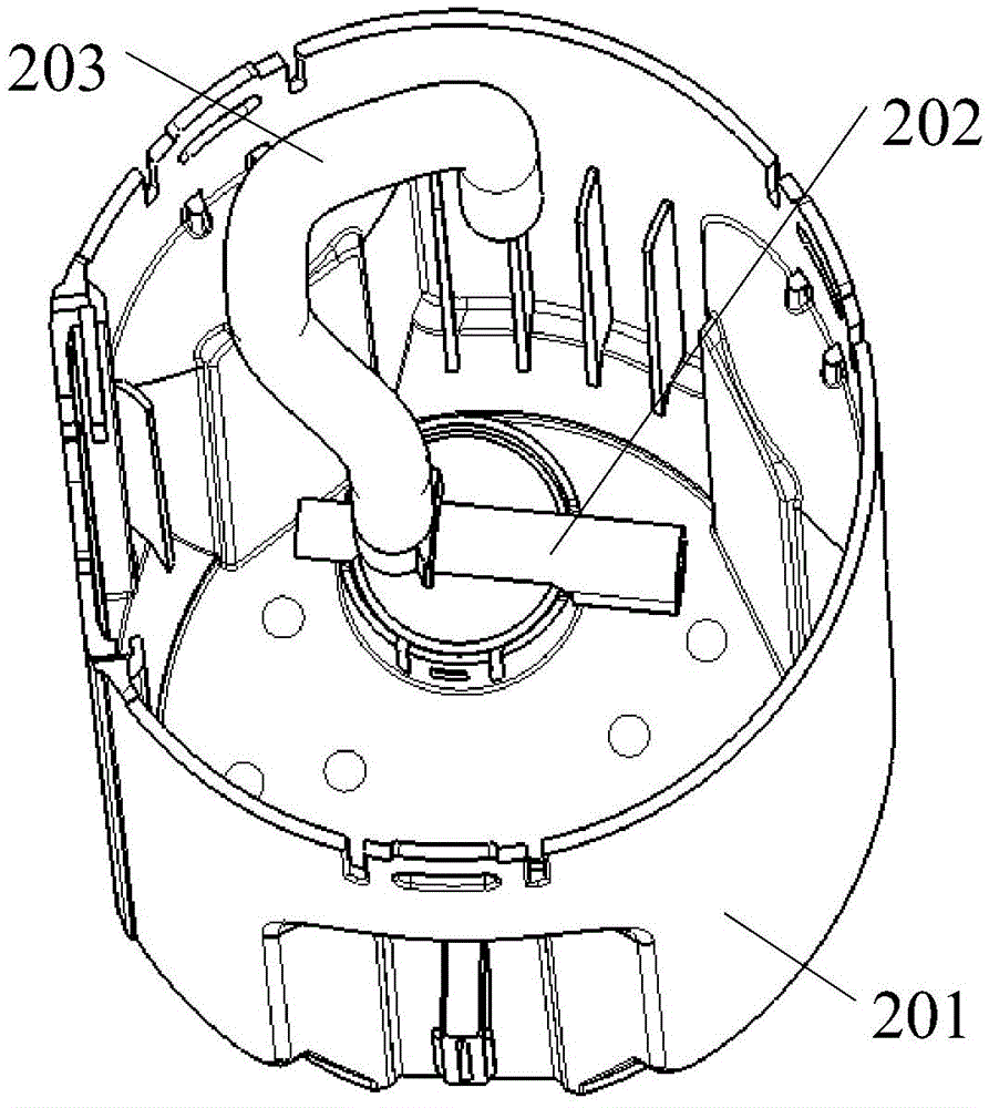
[0031] Please refer to Figure 3-Figure 6 , in a specific embodiment, the oil return structure of the fuel delivery pump provided by the present invention includes an oil storage barrel 201 and an oil return pipe 203 fixed inside the fuel tank, and also includes a three-way pipe 202, and the three-way pipe 202 includes a The first oil inlet 208 of the oil return pipe 203, the oil outlet 210 connected to the oil storage barrel 201 and the second oil inlet 211 connected to the oil outlet 210, between the first oil inlet 208 and the oil outlet 210 are provided Jet pump 209, the jet flow direction of ...


PUM


Abstract

The invention belongs to the technical field of automobile components, and provides an oil transfer pump oil return structure. The oil transfer pump oil return structure comprises an oil storage bucket and an oil return pipe and further comprises a three-way pipe. The oil storage bucket is fixed into a fuel tank. The three-way pipe comprises a first oil inlet communicated with the oil return pipe, an oil outlet communicated with the oil storage bucket and a second oil inlet communicated with the oil outlet. A jet pump is arranged between the first oil inlet and the oil outlet. The jet direction of the jet pump is towards the oil outlet. The first oil inlet is communicated with the oil outlet through the jet pump. The second oil inlet is provided with a pressure valve. The fuel tank is communicated with or isolated from the second oil inlet through the pressure valve. Due to the fact that the three-way pipe is additionally arranged and the jet pump is arranged inside the three-way pipe, negative pressure is formed through the drainage effect, the pressure valve can be switched on through the pressure difference formed between the two sides of the pressure valve, no fuel pressure outside the pressure valve needs to be overcome, the fuel flow utilization rate is improved, the oil return efficiency is improved, and the oil storage bucket can be more rapidly filled with fuel.

Description

technical field [0001] The invention belongs to the technical field of automobile parts, and in particular relates to an oil return structure of an oil delivery pump. Background technique [0002] Due to the different fuel supply required by the engine under different working conditions, in order to ensure the maximum fuel demand of the engine, the rated flow rate of the current fuel pump is designed to be excessive. When working, the excess fuel flows back through the oil return structure of the fuel pump. In the oil storage barrel of the oil pump, and through the drainage effect, the fuel oil outside the oil storage barrel is driven into the oil storage barrel to ensure that the oil storage barrel is full of oil. [0003] The existing oil pump oil return structure is as follows: Figure 1-Figure 2 As shown, the oil storage barrel 101 is fixed in the fuel tank, the oil return pipe 102 is arranged outside the oil storage barrel 101, one end is connected to the pressure regul...

Claims


Application Information

Patent Timeline
Patent Type & Authority Applications(China)
IPC IPC(8): F02M37/00
Inventor 穆海宁吴艳鹏童元
Owner ANHUI JIANGHUAI AUTOMOBILE GRP CORP LTD
Why Eureka
Try Eureka