Drive plate coupling

A technology of couplings and semi-couplings, applied in the direction of couplings, elastic couplings, mechanical equipment, etc., can solve the problems of inconvenient disassembly, inconvenient disassembly, narrow internal space, etc., and achieve convenient disassembly and assembly. Reliable The effect of high performance and simple structure

Inactive Publication Date: 2015-05-20
SHANGHAI HUANGPU MARINE INSTR
View PDF6 Cites 1 Cited by
  • Summary
  • Abstract
  • Description
  • Claims
  • Application Information

AI Technical Summary

Problems solved by technology

For example, the sleeve coupling has a simple structure, is easy to manufacture, and is small in size, but it has high requirements for the installation accuracy of the two shafts and is extremely inconvenient to

Method used


Image

  • Drive plate coupling
  • Drive plate coupling
  • Drive plate coupling

Examples


Embodiment

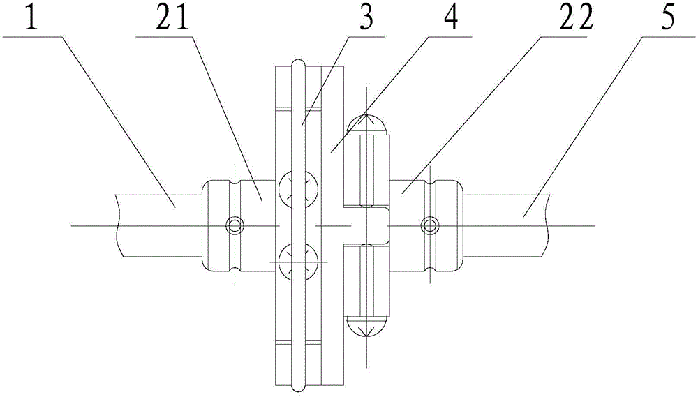
[0019] like figure 1 As shown, a dial coupling, the coupling is respectively connected to the first shaft 1 and the second shaft 5, the coupling includes a left half coupling 21, a right half coupling 22, a spring ring 3 and the cross joint 4, after the first shaft 1 is loaded into the left half coupling 21 and fixed, insert one end of the cross joint 4 into the groove of the left half coupling 21 and install the spring ring 3, and then insert the second The shaft 5 is fixed in the right half coupling 22, and finally the other end of the cross joint 4 is inserted into the groove of the right half coupling 22.

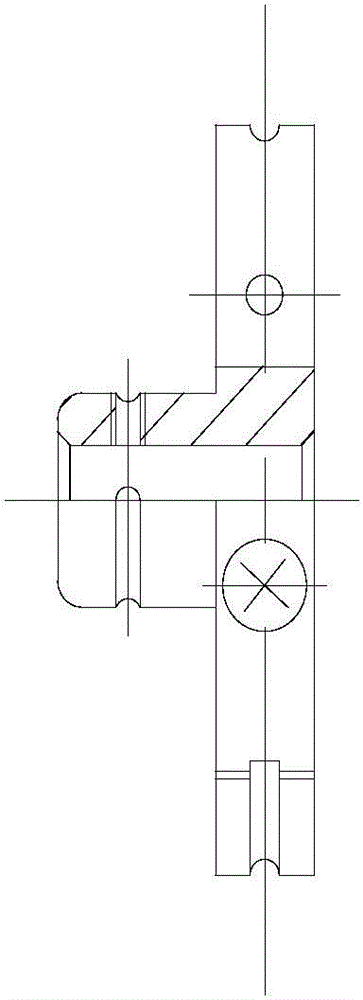
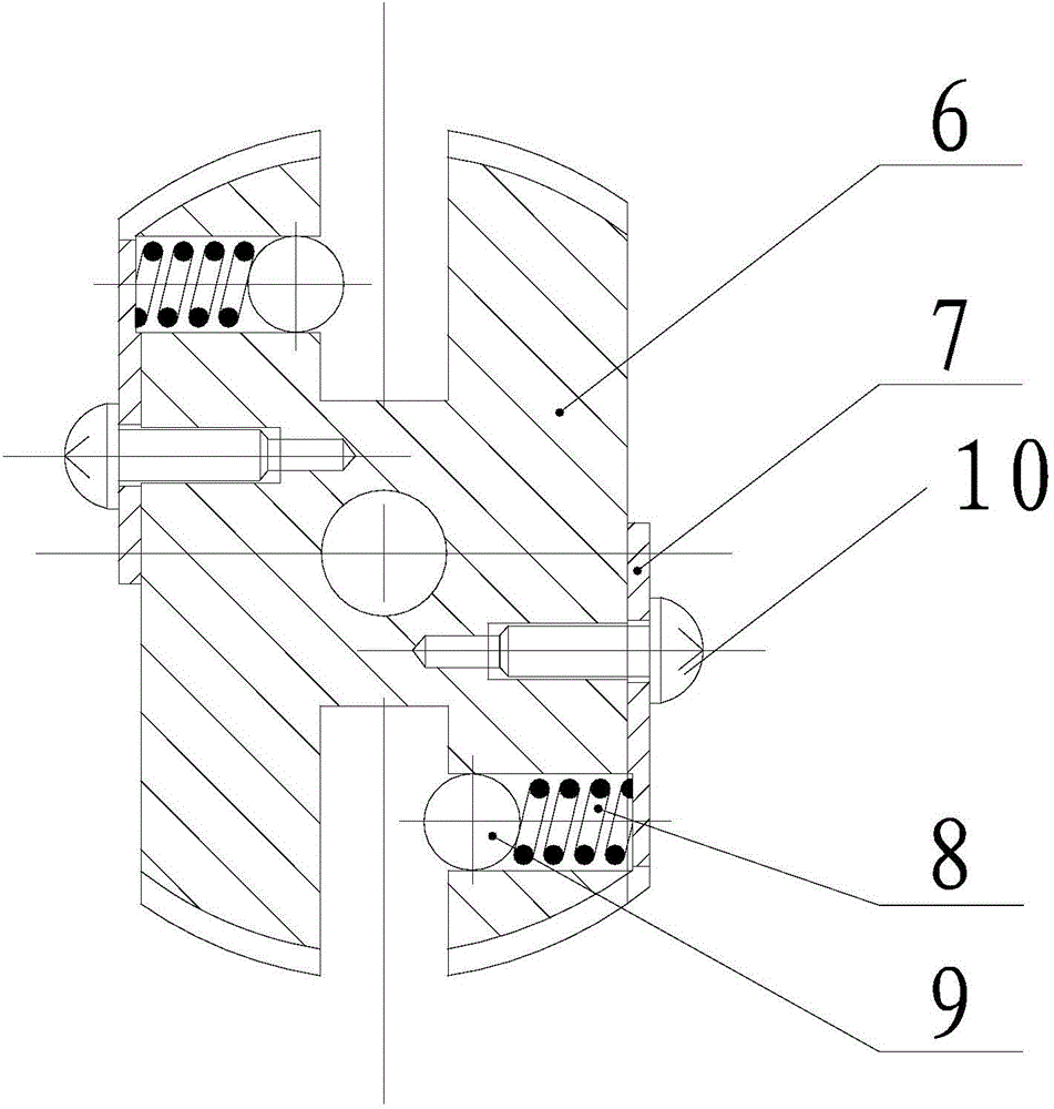
[0020] like figure 2 and 3 As shown, the left half coupling 21 and the right half coupling 22 all include a dial 6, a pressure plate 7, a compression spring 8, a steel ball 9 and a screw 10, and the dial 6 is provided with a cross The joint is inserted into the groove, one end of the compression spring 8 is connected to the pressure plate 7, and the other end is con...


PUM


Abstract

The invention relates to a drive plate coupling. The coupling is connected with a first shaft and a second shaft and comprises a left half coupling body, a right half coupling body, a spring ring and a cross joint, wherein after the first shaft is installed in the left half coupling body and fixed, one end of the cross joint is inserted in a groove of the left half coupling body and provided with the spring ring, then, the second shaft is installed in the right half coupling body and fixed, and finally, the other end of the cross joint is inserted in a groove of the right half coupling body. Compared with the prior art, the drive plate coupling has the advantages of being simple in structure, low in cost, convenient to disassemble and assemble, high in reliability and the like.

Description

technical field [0001] The invention relates to a shaft coupling, in particular to a dial coupling. Background technique [0002] As we all know, the main function of the coupling is to connect the two shafts and transmit torque, and can properly compensate the radial and axial errors between the two shafts caused by manufacturing, installation and other factors. [0003] At present, there are many types of couplings on the market, each with its own relative advantages and disadvantages. For example, the sleeve coupling has a simple structure, is easy to manufacture, and is small in size, but it has high requirements for the installation accuracy of the two shafts and is extremely inconvenient to disassemble. Therefore, for some precision instruments with narrow internal space and inconvenient disassembly and assembly, the existing couplings on the market are difficult to meet the actual use requirements. Contents of the invention [0004] The object of the present inven...

Claims


Application Information

Patent Timeline
IPC IPC(8): F16D3/10
Inventor 刘东生龚建平
Owner SHANGHAI HUANGPU MARINE INSTR
Why Eureka
Try Eureka