Low-temperature pneumatic valve time delay unit

A technology of pneumatic valve and delay device, which is used in valve details, valve devices, engine components, etc. to achieve high reliability, long service life, and prevent water hammer.

Inactive Publication Date: 2015-05-20
ENG DESIGN & RES INST OF GENERAL ARMAMENTS DEPT
View PDF9 Cites 4 Cited by
  • Summary
  • Abstract
  • Description
  • Claims
  • Application Information

AI Technical Summary

Problems solved by technology

Therefore, if the delay device applied to the fire extinguishing system is applied to the cryogenic valve, it obviously cannot meet the above requirements.

Method used


Image

  • Low-temperature pneumatic valve time delay unit
  • Low-temperature pneumatic valve time delay unit
  • Low-temperature pneumatic valve time delay unit

Examples


Embodiment Construction

[0026] The present invention will be described in further detail below in conjunction with the accompanying drawings and specific embodiments.

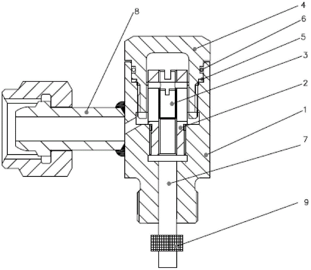
[0027] Such as figure 1 As shown, the embodiment of the pneumatic valve delayer of the present invention includes a valve body 1 , a valve core 2 , an adjustment rod 3 , a pressure cap 4 , an air inlet pipe 7 , an air outlet pipe 8 , and a filter 9 .

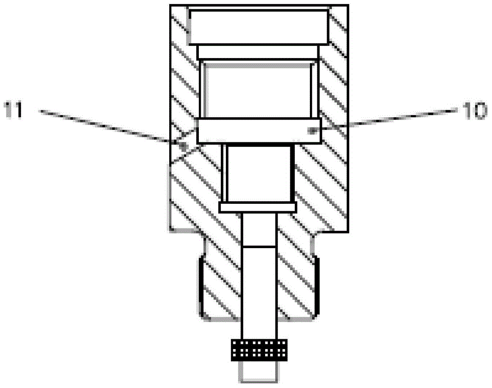
[0028] figure 2 The structure of the valve body of the pneumatic valve delayer is shown. The valve body 2 includes an annular air guide groove 10 expanding inwardly in the middle of the inner cavity, and the air guide groove divides the inner cavity of the valve into upper and lower parts. , the lower part of the inner cavity is the end connected with the valve core, and the upper part of the inner cavity is the end connected with the pressure cap. One side of the air guide groove is provided with an oblique air hole 11 through which gas can enter the air outlet.
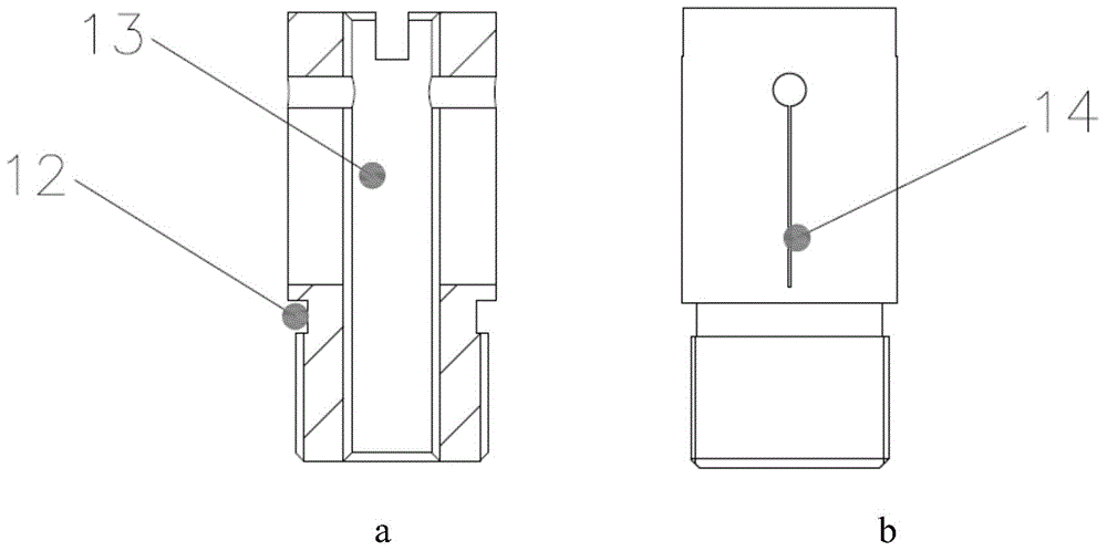
[0029] image 3 ...


PUM


Abstract

A low-temperature pneumatic valve time delay unit belongs to the technical field of pneumatic control. The time delay unit comprises a gas inlet, a filter, a gas outlet, a valve body, a valve element, an adjusting rod and a pressing cover, wherein the valve body is provided with a flow guide groove and a gas hole. After the low-temperature pneumatic valve time delay unit is arranged in a pneumatic valve starting gas pipeline, gas needs to pass through the gas inlet and the filter to enter the valve element, passes through a throttling opening in the valve element to flow into a gas cavity formed by the valve body, the valve element, the pressing cap and the flow guide groove, and then flows into the gas outlet from one side of the valve body so as to enter a valve pneumatic execution mechanism to drive the valve to be opened and closed. The position of screwing the adjusting rod into the valve element is adjusted so that the gas flow of the gas entering the valve pneumatic execution mechanism can be controlled, and furthermore, the valve obtains different opening and closing delaying time. The low-temperature pneumatic valve time delay unit is compact and reasonable to assembly and is simple and convenient to operate in a use process; the adjustable range is wide and the time delaying function is stable.

Description

technical field [0001] The invention belongs to the technical field of pneumatic control, in particular to a delay device for adjusting the opening and closing time of a low-temperature pneumatic valve. Background technique [0002] With the development and large-scale application of cryogenic technology, cryogenic valves are used more and more widely in various fields such as space launch, liquefied natural gas storage and transportation, and air separation. Due to the certain safety hazards in low temperature sites, the low temperature valves in large industrial sites generally use pneumatic methods to realize automatic remote control. That is, compressed air or nitrogen is used as the power source, and the action command is triggered manually or automatically to make the intake and exhaust solenoid valves act, supply and discharge compressed gas to the actuator, and the compressed gas acts on the piston or diaphragm to overcome the valve action. The frictional force and ...

Claims


Application Information

Patent Timeline
Patent Type & Authority Applications(China)
IPC IPC(8): F16K31/14F16K47/02F16K47/04
CPCF16K31/143F16K47/02F16K47/04
Inventor 张亮亮陈虹孙庆国高旭刘岩云李爱华雷刚邱小林邢科伟
Owner ENG DESIGN & RES INST OF GENERAL ARMAMENTS DEPT
Why Eureka
Try Eureka