Method of detecting state of ultrasonic flowmeter

A state detection and flowmeter technology, applied in the direction of measuring flow/mass flow, liquid/fluid solid measurement, measuring devices, etc., can solve the problem that the echo signal cannot be received within a certain period of time, the ultrasonic flowmeter cannot work normally, and the receiving No echo signal and other problems, to achieve the effect of simplifying the inspection and maintenance process

Active Publication Date: 2015-05-20
姜跃炜
View PDF6 Cites 8 Cited by
  • Summary
  • Abstract
  • Description
  • Claims
  • Application Information

AI Technical Summary

Problems solved by technology

However, when the circuit, the transducer is damaged, the fluid in the pipeline contains a lot of air, or even the water stops causing the pipeline to be empty, etc., there will be problems in the reception of the echo signal, and the echo signal cannot be received within a certain period of time or cannot be received at all. The echo signal cannot be received, resulting in the failure of the ultrasonic flowmeter to work normally
Therefore, it is very important to accurately know the working status of the ultrasonic flowmeter for the maintenance and repair of the ultrasonic flowmeter, but there is no good state detection method applied to the ultrasonic flowmeter at present.

Method used


Image

  • Method of detecting state of ultrasonic flowmeter
  • Method of detecting state of ultrasonic flowmeter
  • Method of detecting state of ultrasonic flowmeter

Examples


Embodiment Construction

[0013] The present invention will be further elaborated below in conjunction with the accompanying drawings.

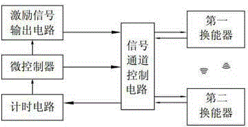
[0014] see figure 1 , At least a microcontroller, a timing circuit, an excitation signal output circuit, a signal channel control circuit, a first transducer and a second transducer are arranged in the detection system of the ultrasonic flowmeter. Among them, the micro-controller is used to systematically control the work of each circuit module in the ultrasonic flowmeter, and the obtained timing data is combined with other factors such as temperature and flow tube section to comprehensively calculate the fluid volume; the excitation signal output circuit is used to output excitation and transmit energy The excitation signal of the transducer; the signal channel control circuit is used to selectively connect the excitation signal to the first transducer / second transducer to achieve the purpose of measuring the forward / countercurrent flow velocity; while the existing t...


PUM


Abstract

The invention belongs to the field of ultrasonic flow detection and particularly relates to a method of detecting the state of an ultrasonic flowmeter. According to the method, aftershock generated by a piezoceramic plate of an ultrasonic transducer after an exciting signal stops acting imparts after-wave to the exciting signal, transducer faults can be judged or troubleshot quickly just by subjecting the flowmeter to circuit detection in the tube emptiness or fault state, the tube emptiness state or fault causes are further ensured, and the maintenance process of the ultrasonic flowmeter is greatly simplified.

Description

technical field [0001] The invention belongs to the field of ultrasonic flow detection, and in particular relates to a state detection method for an ultrasonic flow meter. Background technique [0002] The ultrasonic flowmeter manufactured by the principle of time difference method is one of the popular ultrasonic flowmeter design methods at present. Its design principle is as follows: a fluid measurement pipeline equipped with a two-way ultrasonic transceiver integrated transducer, alternately transmits ultrasonic signals in the downstream and countercurrent directions and receives ultrasonic waves to generate echo signals, and calculates the ultrasonic wave in the fluid. The propagation time difference generated by the alternation. Afterwards, the fluid flow in the pipeline is calculated by the relevant conversion mathematical model. However, when the circuit, the transducer is damaged, the fluid in the pipeline contains a lot of air, or even the water stops causing ...

Claims


Application Information

Patent Timeline
Patent Type & Authority Applications(China)
IPC IPC(8): G01F25/00G01F1/66
Inventor 姜跃炜
Owner 姜跃炜
Why Eureka
Try Eureka