

Display drive circuit and display device
A display drive and circuit technology, applied to static indicators, instruments, etc., can solve the problems of source line convergence time delay, gray line convergence reduction, etc.
- Summary
- Abstract
- Description
- Claims
- Application Information
AI Technical Summary
Problems solved by technology
Method used
Image

Examples
Embodiment approach 1
[0103] [Embodiment 1]
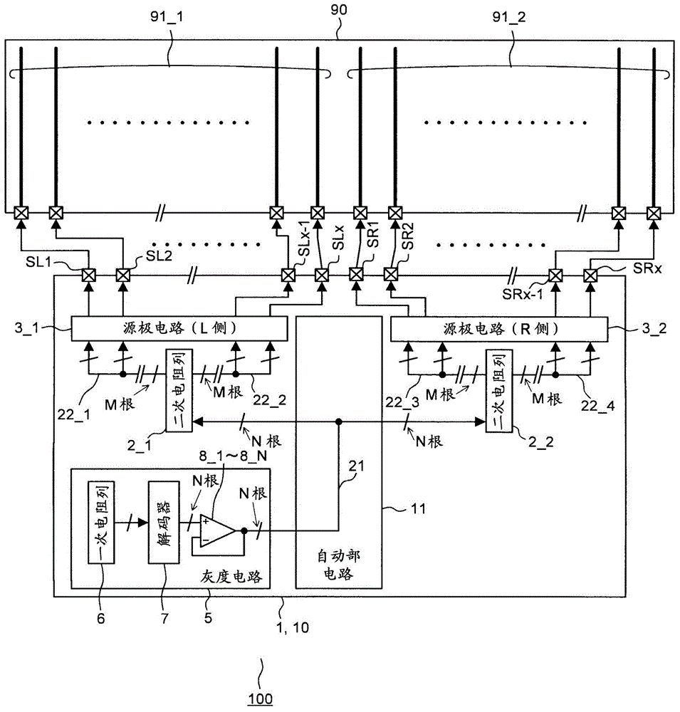
[0104] figure 1 It is a block diagram showing a configuration example of the display driving circuit 1 and the display device 100 according to the first embodiment. and, figure 2 It is a block diagram showing a configuration example of a conventional display driving circuit 1 and a display device 100 as a comparative example.
[0105] first of all, yes figure 2 The configuration of a conventional display device 100 shown as a comparative example will be described. The display device 100 is configured to include: a display panel 90 including a plurality of source lines 91_1 and 91_2; and a display drive circuit 1 connected to the display panel 90 and including a plurality of source electrodes capable of driving the plurality of source lines 91_1 to 91_2, respectively. Amplifier 4 (not shown). The display panel 90 is an active matrix display panel, such as a liquid crystal display panel or an organic EL display panel. To display pixels selected b...
Embodiment approach 2
[0139] [Embodiment 2]
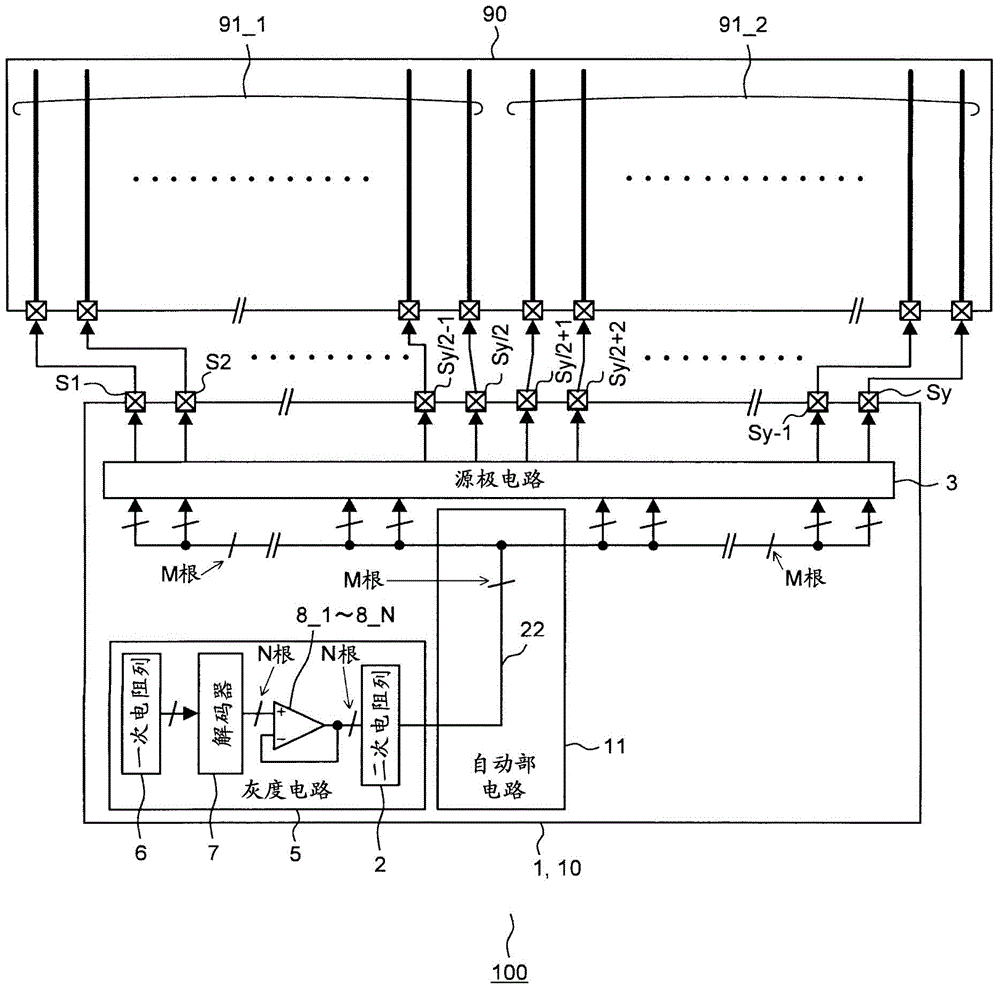
[0140] In Embodiment 1, the following display driving circuit 1 is mainly described. The source circuit 3 is divided into two left and right source circuits (L side) 3_1 and source circuits (R side) 3_2, and the source circuits (R side) 3_2 are respectively corresponding to each other. The secondary resistor columns (2nd resistor strings) 2_1 and 2_2 are provided, but it is also possible to divide the source circuit 3 into a plurality of parts and provide the same number of secondary resistor columns 2 correspondingly.
[0141] Figure 8 It is a block diagram showing a configuration example of the display driving circuit 1 according to the second embodiment. The source circuit 3 is an example divided into four parts. The display driver circuit 1 is formed on a single semiconductor substrate, and can also be realized as a display driver IC 10 . The display driver circuit 1 or display driver IC 10 is composed of a gray scale circuit 5, an automatic pa...
Embodiment approach 3
[0150] [Embodiment 3]
[0151] In Embodiment 1 and Embodiment 2 above, the case where the display driver circuit 1 is formed on a single semiconductor substrate and realized by the display driver IC 10 of one chip has been mainly described, but it can also be realized in multiple chips. . In Embodiment 3, the case of dividing into two chips is mainly described, but the case of dividing into two or more chips can be similarly implemented.
[0152] Figure 10 It is a block diagram showing a display driver circuit 1 and a configuration example of a display device 100 using the display driver circuit 1 as a comparative example of a conventional two-chip configuration, Figure 11 It is a block diagram showing a configuration example of the display driving circuit 1 according to the third embodiment.
[0153] First, from Figure 10 The configuration of a conventional display device 100 shown as a comparative example will be described. The display device 100 is configured to in...
PUM
 Abstract
Description
Claims
Application Information