Supercharge Your Innovation With Domain-Expert AI Agents!

cooling mechanism

A cooling mechanism and cooling chamber technology, applied in the manufacture of electrical components, circuits, semiconductor/solid-state devices, etc., can solve the problems of chip contact and insufficient spacing, and achieve the effect of reducing cooling air, cost and environmental load

Active Publication Date: 2019-01-01
DISCO CORP
View PDF6 Cites 0 Cited by
  • Summary
  • Abstract
  • Description
  • Claims
  • Application Information

AI Technical Summary

Problems solved by technology

Therefore, for example, when the chip size is different in vertical and horizontal directions, in the first direction (for example, the longitudinal direction of the chip) and the second direction (for example, the lateral direction of the chip), the intervals formed between the chips will be different, even in one direction A sufficient gap is formed in one direction, and the gap in the other direction is also insufficient, so that there is a possibility of contact between adjacent chips when processing the workpiece
In addition, when the workpiece is made of a material with high ductility, there is also a problem that the sheet is not easily broken even if it expands.

Method used


Image

  • cooling mechanism
  • cooling mechanism
  • cooling mechanism

Examples


Embodiment Construction

[0113] 1. Structure of the expansion device

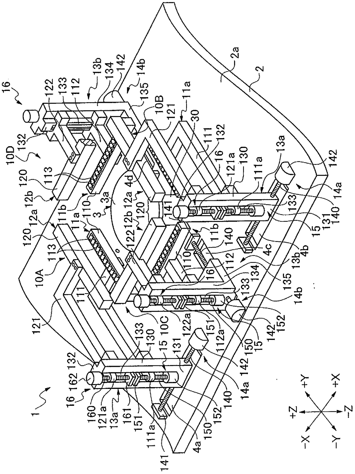
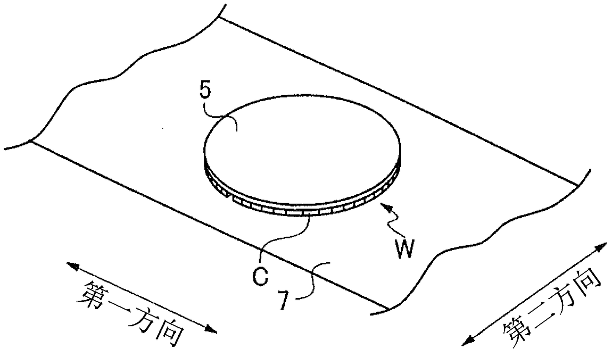
[0114] figure 1 The shown expansion device 1 is, for example, capable of figure 2 The illustrated example of an expansion device that expands the expansion sheet 7 on which the workpiece W is pasted is expanded. The expansion device 1 has a device base 2 , and a holding table 3 is supported up and down at the center of an upper surface 2 a of the device base 2 via a table support 30 . The holding table 3 holds a workpiece W via an expansion sheet 7 . The upper surface of the holding table 3 serves as a holding surface 3a on which the workpiece W is held.

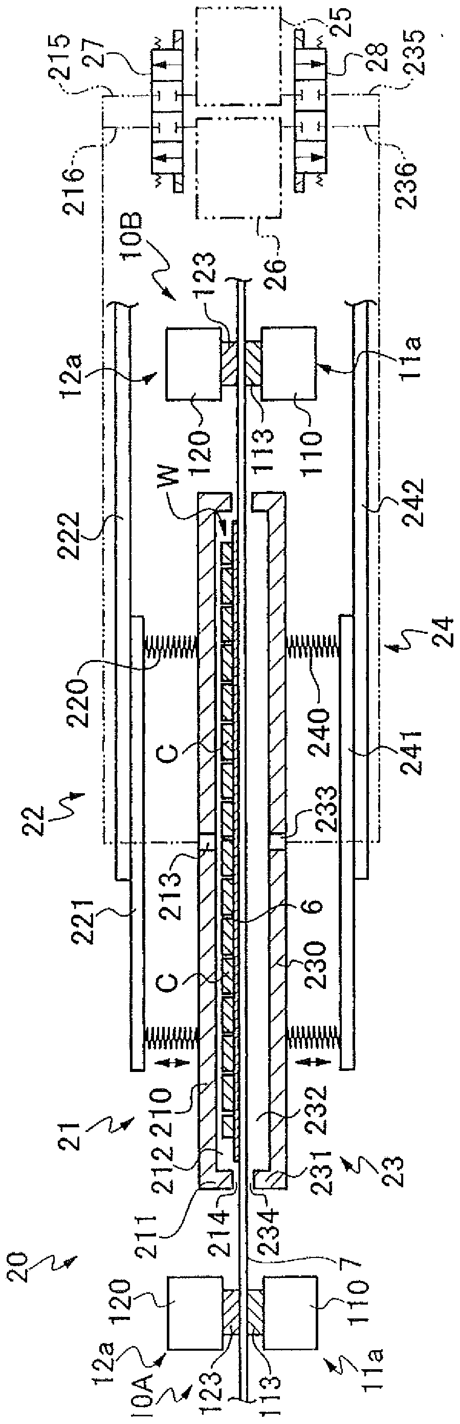
[0115] On the upper surface 2a of the device base 2, a first clamping member 10A and a second clamping member 10B are arranged to face each other across the holding table 3 in the first direction. The first clamping member 10A and the second clamping member 10A Two clamping members 10B enable figure 2 The expansion sheet 7 shown expands in the ±X direction (first direction)...


PUM


Abstract

The invention provides a segmentation method and a cooling mechanism applied during the segmentation method. By means of the segmentation method, a space between two chips is ensured to be large enough. The segmentation method comprises the steps of clamping expansion pieces (7) at the periphery of a to-be-machined object (W) by means of a first clamping member (10A), a second clamping member (10B), a third clamping member (10C) and a fourth clamping member (10D); injecting the cooling air towards the back sides of the expansion pieces and the front side (Wa) of the to-be-machined object so as to cool the to-be-machined object; and cutting the to-be-machined object. In this way, the to-be-machined object is accurately cut.

Description

technical field [0001] The present invention relates to a dividing method for dividing a workpiece having a dividing origin formed therein, and a cooling mechanism capable of cooling the workpiece in the dividing method. Background technique [0002] For a workpiece such as a semiconductor wafer, devices are formed in regions divided by grid-shaped planned dividing lines on the front surface, and are divided along the planned dividing lines to be divided into individual device chips having devices. As a method of dividing a workpiece into individual device chips, a method has been proposed in which a laser beam of a wavelength that is transparent to the workpiece is positioned inside the workpiece corresponding to the dividing line, and along the A modified layer is formed inside the workpiece by irradiating laser light on the line to be divided, and then an external force is applied to the workpiece to divide the workpiece (see, for example, Patent Document 1 below). [00...

Claims


Application Information

Patent Timeline
IPC IPC(8): H01L21/301H01L21/67
Inventor 高泽徹
Owner DISCO CORP
Features
  • R&D
  • Intellectual Property
  • Life Sciences
  • Materials
  • Tech Scout
  • Unparalleled Data Quality
  • Higher Quality Content
  • 60% Fewer Hallucinations
Learn More