Frequency offset calibration method and equipment

A calibration method and frequency offset technology, applied in the field of communication, can solve problems such as large differences in antenna frequency offset and inaccurate frequency offset estimation

Active Publication Date: 2015-05-20
DATANG MOBILE COMM EQUIP CO LTD
View PDF7 Cites 7 Cited by
  • Summary
  • Abstract
  • Description
  • Claims
  • Application Information

AI Technical Summary

Problems solved by technology

[0008] The invention provides a frequency offset calibration method, which is used to solve the problem of inaccurate frequency offset estimation caused by the large frequency offset difference of each antenna, and to ensure the demodulation performance in a high-speed environment

Method used


Image

  • Frequency offset calibration method and equipment
  • Frequency offset calibration method and equipment
  • Frequency offset calibration method and equipment

Examples


Embodiment Construction

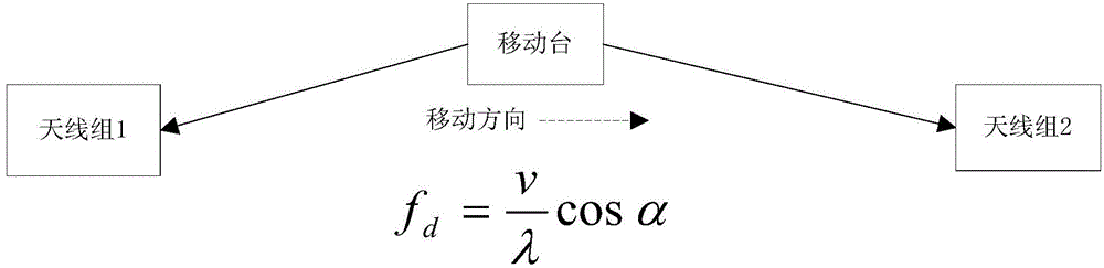
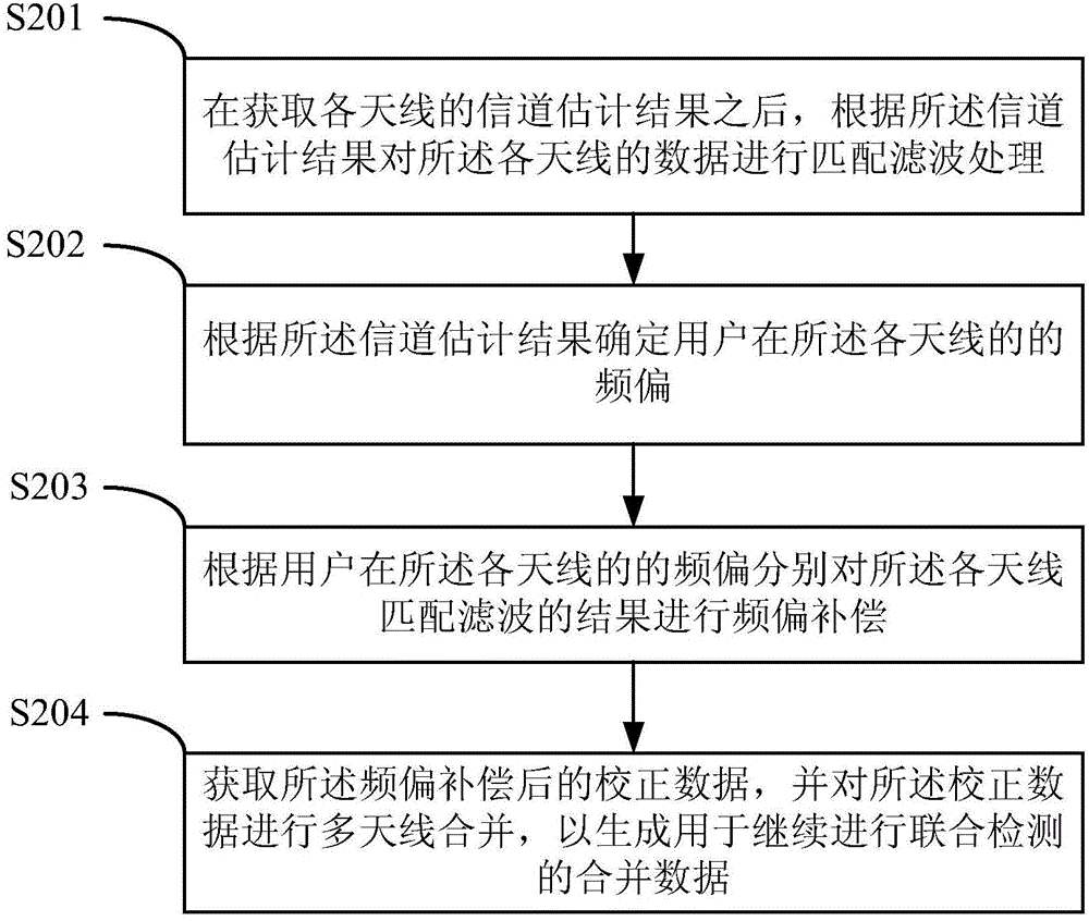
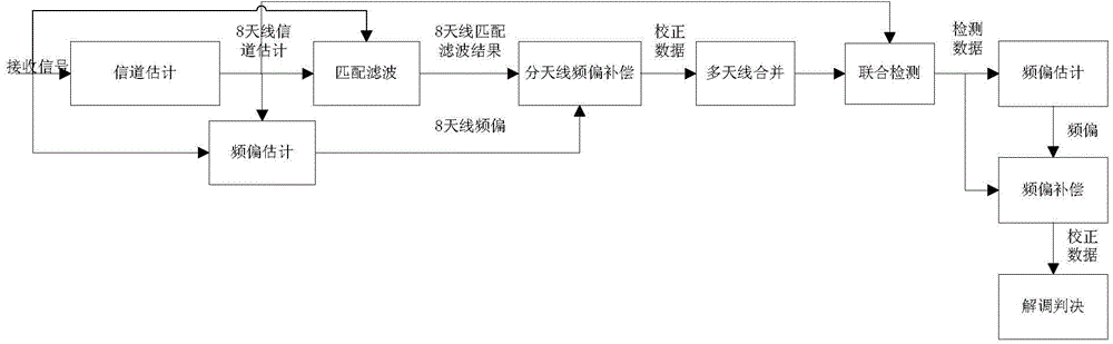
[0041] In view of the problems raised in the background technology, the present invention proposes a frequency offset calibration method. In the uplink time slot, the channel estimation results are used to estimate the frequency offset of each antenna, and the regression average is performed. After each antenna is matched and filtered, multiple Before the antenna data is combined, the frequency offset compensation is performed on the data of each antenna separately, so as to solve the problem of inaccurate frequency offset estimation caused by the large frequency offset difference of each antenna, and ensure the demodulation performance in the high-speed environment. Such as figure 2 As shown, the method includes the following steps:

[0042] S201. After acquiring the channel estimation result of each antenna, perform matched filtering processing on the data of each antenna according to the channel estimation result.

[0043] In a preferred embodiment of the present inventio...


PUM


Abstract

The invention relates to a frequency offset calibration method. The method comprises the following steps: performing matched filtering processing on the data of each antenna according to channel estimation results after acquiring the channel estimation result of each antenna; performing frequency offset compensation on the matched filtering result of each antenna respectively according to the frequency offset of a user on each antenna; acquiring correction data after frequency offset compensation, and performing multi-antenna combination on the correction data. By adopting the frequency offset calibration method, the problem of incapability of evaluating an accurate frequency offset estimation value by averaging a plurality of antennas caused by large frequency offset difference among the antennas of distributed antennas is solved, the accuracy of frequency offset estimation is increased, and the demodulation performance is ensured.

Description

technical field [0001] The invention relates to the technical field of communications, in particular to a frequency offset calibration method. The invention also relates to a frequency offset calibration device. Background technique [0002] With the development of high-speed railways, distributed antennas are widely used as a network coverage solution in high-speed mobile environments. They are mainly used to expand the coverage of a single cell and avoid call drops and user experience degradation caused by frequent cell switching. question. [0003] Such as figure 1 As shown in , it is a schematic diagram of the application of existing distributed antennas in high-speed scenarios, where F d =(V / λ)*COSа is the Doppler frequency shift formula, in which V is the moving speed of the mobile station; λ is the radio wavelength; а represents the angle between the incident wave and the moving direction of the mobile station. For a mobile station that adopts a distributed antenn...

Claims


Application Information

Patent Timeline
Patent Type & Authority Applications(China)
IPC IPC(8): H04L25/03H04L25/02
Inventor 修凯王文静姜朋娟
Owner DATANG MOBILE COMM EQUIP CO LTD
Why Eureka
Try Eureka