Rolling bearing with sealing subassembly
A technology for rolling bearings, sealing components, applied in the direction of ball bearings, bearing elements, shafts and bearings
- Summary
- Abstract
- Description
- Claims
- Application Information
AI Technical Summary
Problems solved by technology
Method used
Image

Examples
Embodiment Construction
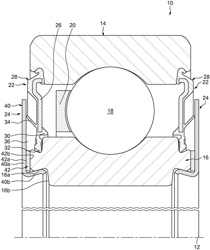
[0018] Such as figure 1 , which shows an embodiment of a rolling bearing 10 according to a first example of the invention, said rolling bearing (having an axis 12) comprising an outer ring 14, an inner ring 16, a plurality of rolling elements arranged between said rings 18 (balls in this case), and a cage 20 for keeping the rolling elements circumferentially spaced apart. The rolling bearing 10 also comprises an annular seal 22 and an annular seal assembly 24 on each side to close the radial gap existing between these rings 14 , 16 .
[0019] Said inner ring 16 and outer ring 14 are concentric and symmetrical with respect to a transverse radial plane passing through the center of the rolling bearing 10 . The ring is of solid type. One of the rings rotates while the other ring is fixed or also rotates. The outer ring 14 comprises an annular circular raceway formed onto its bore and two annular recesses or grooves formed radially from the bore towards the outside and arrange...
PUM
 Abstract
Description
Claims
Application Information
 - Generate Ideas
- Intellectual Property
- Life Sciences
- Materials
- Tech Scout
- Unparalleled Data Quality
- Higher Quality Content
- 60% Fewer Hallucinations
Browse by: Latest US Patents, China's latest patents, Technical Efficacy Thesaurus, Application Domain, Technology Topic, Popular Technical Reports.
© 2025 PatSnap. All rights reserved.Legal|Privacy policy|Modern Slavery Act Transparency Statement|Sitemap|About US| Contact US: help@patsnap.com