Mop cleaning dewaterer

A mop cleaning and dehydrating machine technology, applied in cleaning machinery, cleaning carpets, cleaning floors, etc., can solve the problem that the mop cannot be cleaned conveniently, and achieve the effects of preventing large vibration, improving cleaning effect, and preventing vibration

Inactive Publication Date: 2015-05-27
CHINA THREE GORGES UNIV
View PDF0 Cites 4 Cited by
  • Summary
  • Abstract
  • Description
  • Claims
  • Application Information

AI Technical Summary

Problems solved by technology

[0003] The technical problem to be solved by the present invention is to provide a mop cleaning and dehydrating machine for the deficiencies of the above-mentioned prior art, which can solve the problem that the mop cannot be cleaned conveniently

Method used


Image

  • Mop cleaning dewaterer
  • Mop cleaning dewaterer
  • Mop cleaning dewaterer

Examples


Embodiment Construction

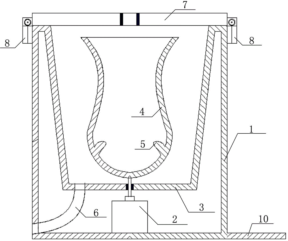
[0024] Such as figure 1 A mop cleaning and dehydrating machine is shown, which includes a case 1, a motor 2 is arranged at the bottom of the case 1, an inner tank 4 is arranged in the case 1, and the bottom end of the inner tank 4 is fixedly connected with the end of the rotor of the motor 2; the inner tank 4 A raised structure 5 is provided in the middle.

[0025] The case 1 is provided with an inner cylinder 3, the upper edge of the case 1 is connected with the upper edge of the inner cylinder 3, and the inner liner 4 is arranged in the inner cylinder 3; the inner liner 4 is a mesh structure; the inner cylinder 3 is connected to the chassis 1 through a drain pipe 6.

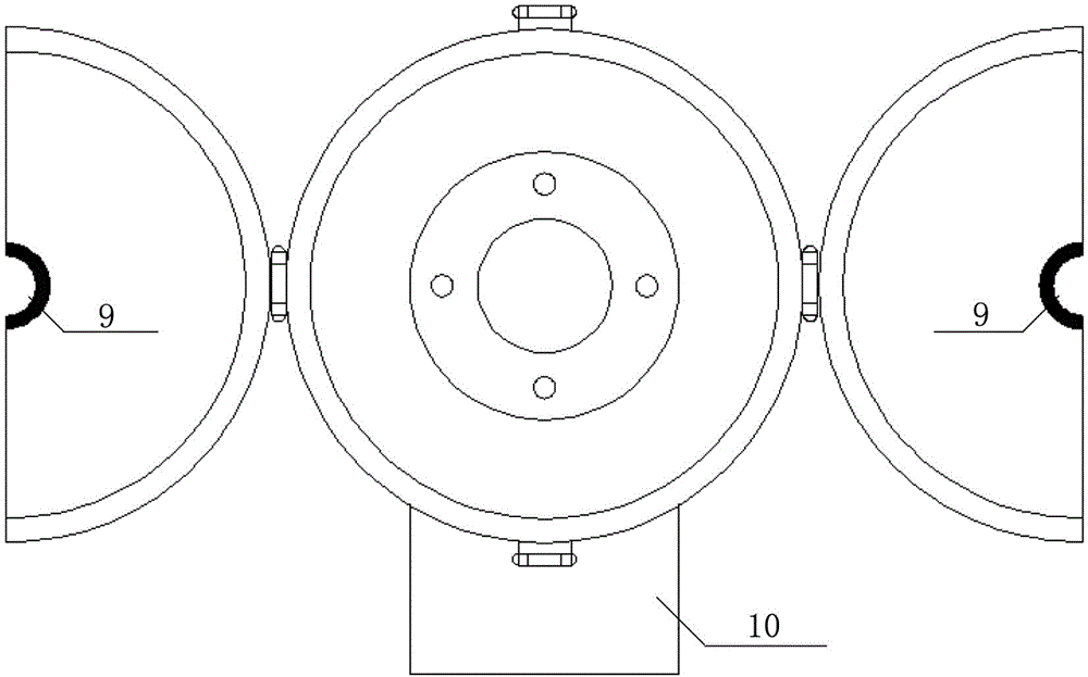
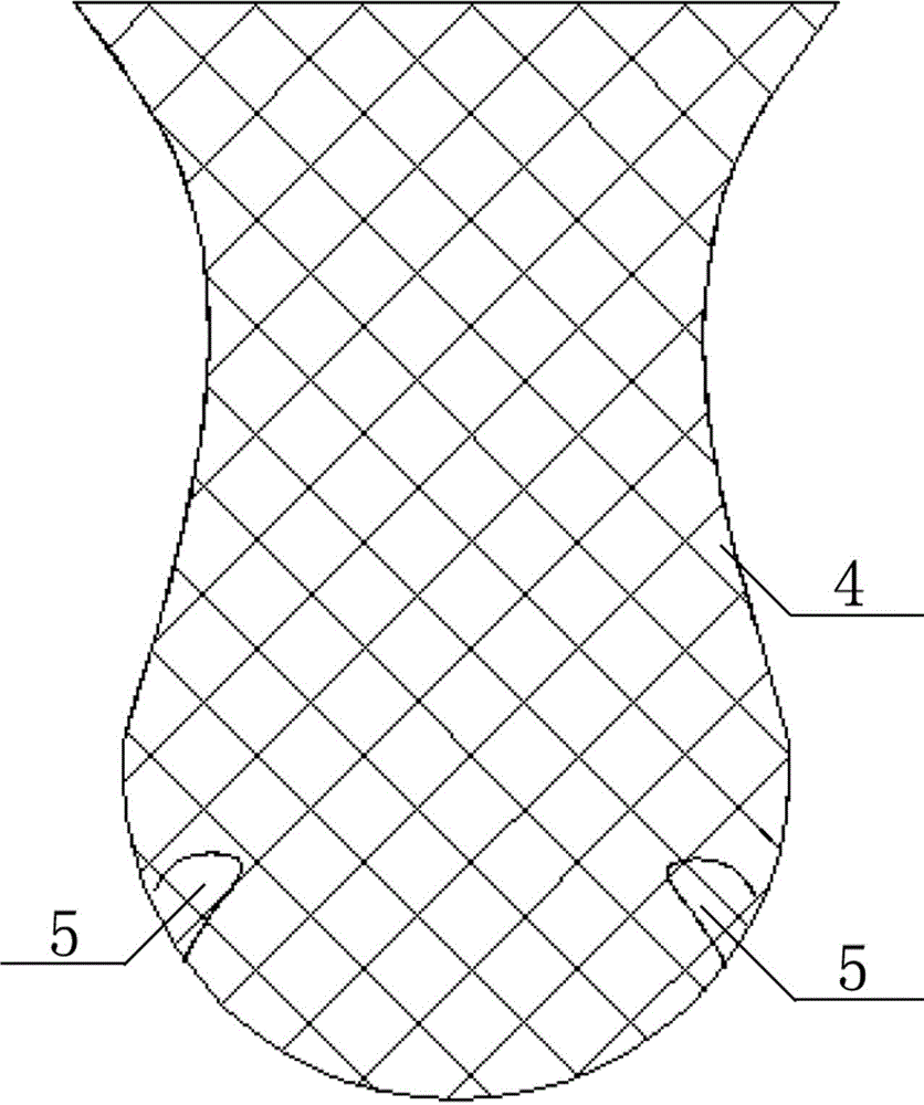
[0026] There are four protruding structures 5, which are symmetrically distributed on the inner wall of the inner liner 4.

[0027] Such as image 3 As shown, the bladder wall of the inner bladder 4 has a concave curved shape in the middle.

[0028] A bucket cover 7 is provided at the upper opening of the chassis 1, ...


PUM


Abstract

A mop cleaning dewaterer comprises a case. A motor is arranged at the inner bottom of the case, an inner container is arranged in the case, the bottom end of the inner container is fixedly connected with the end of a motor rotor, and a projecting structure is arranged in the inner container. A mop is placed into the inner container, the motor drives the inner container to rotate, the mop can be effectively cleaned, the projecting structure can drive water to rotate when the inner container rotates, and the mop is scrubbed.

Description

Technical field [0001] The invention belongs to the field of daily necessities, and specifically relates to a mop cleaning and dehydrating machine. Background technique [0002] The mop has become an indispensable appliance in home life. Almost all homes and various life and work occasions use mops, but at the same time, many users are worried about the inconvenience of cleaning the mop and drying the mop. The mop is dirty and it is inconvenient to rub and wash with your hands, but it can't be cleaned when you wash it directly with water; and sometimes when you rush to mop the floor, the mop is still dripping, which is very inconvenient to use. Summary of the invention [0003] The technical problem to be solved by the present invention is to address the above-mentioned shortcomings of the prior art, and provides a mop cleaning and dewatering machine, which can solve the problem that the mop cannot be easily cleaned. [0004] The purpose of the present invention is achieved as foll...

Claims


Application Information

Patent Timeline
IPC IPC(8): A47L13/58
Inventor 鲁君成江龙芝鲁玉龙
Owner CHINA THREE GORGES UNIV
Why Eureka
Try Eureka