

Feeding device with pneumatic clamping jaw
A technology of pneumatic grippers and feeding devices, applied in the direction of conveyor objects, transportation and packaging, etc., can solve problems such as instability, low feeding efficiency, single applicable parts, etc., achieve collision avoidance, strong versatility, and shorten waiting time Effect
- Summary
- Abstract
- Description
- Claims
- Application Information
AI Technical Summary
Problems solved by technology
Method used
Image

Examples
Embodiment 1
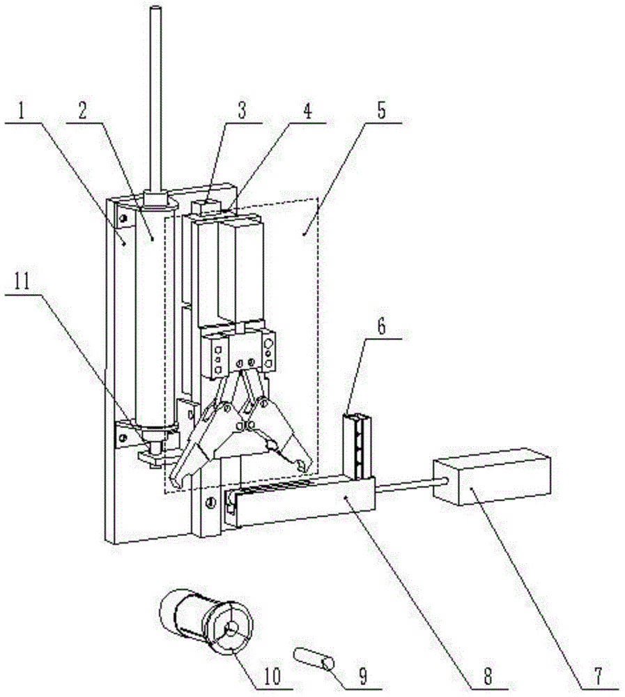
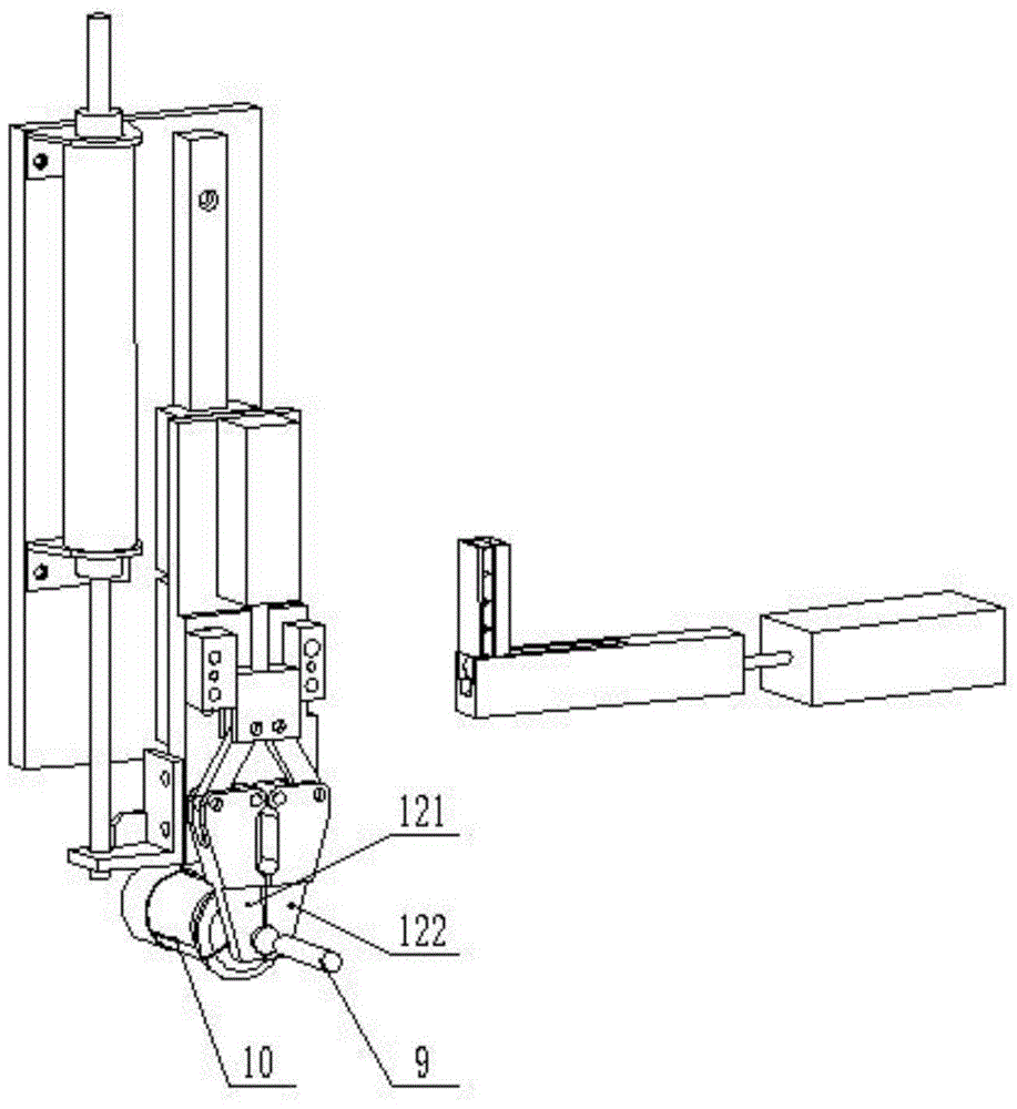
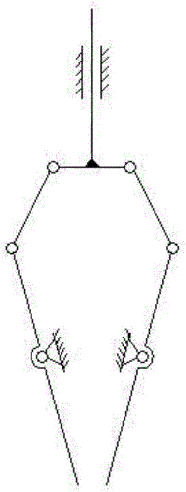
[0024] Pneumatic gripper feeding device, as shown in the accompanying drawings, comprises pneumatic gripper 5, collet 10 and feeding arm 8, and pneumatic gripper 5 comprises base 16, and base 16 is provided with first cylinder 15, and the first cylinder 15 The piston rod is threadedly connected with a slide plate 14, the slide plate 14 is hinged with a left connecting rod 131 and a right connecting rod 132, and the left connecting rod 131 and the right connecting rod 132 are respectively hinged with a left clamp finger 121 and a right clamp finger 122. The finger 121 and the right gripper finger 122 are both hinged on the base. One end of the feed arm 8 is provided with a first groove 22 that can only accommodate one blank 19. The feed arm 8 can move to the bottom of the pneumatic gripper 5, and the pneumatic gripper 5 can move to above the axis of the collet 10. When the piston rod of the first cylinder 15 is retracted, it pushes the slide plate 14 to move downward, and the s...
PUM
 Abstract
Description
Claims
Application Information