
Novel wringing roller changing device

A roll changing device and roll drying technology, which is applied in transportation and packaging, metal processing, load hanging components, etc., can solve the problems of time-consuming and labor-intensive adjustment of the counterweight by twisting the screw by the hand wheel, and the inability to fix the shaft head stably, etc., to achieve The effect of avoiding waste and improving production efficiency

Active Publication Date: 2015-05-27
WISDRI ENG & RES INC LTD
View PDF6 Cites 11 Cited by
  • Summary
  • Abstract
  • Description
  • Claims
  • Application Information

AI Technical Summary

Problems solved by technology

However, the roll changing device in the form of a full-circle sleeve requires multiple manual adjustments to insert the shaft head into the sleeve, and the set bolts only withstand a point on the outer peripheral surface of the shaft head, which cannot fix the shaft head firmly. It is time-consuming and labor-intensive to adjust the counterweight by twisting the screw by the hand wheel

Method used


Image

  • Novel wringing roller changing device
  • Novel wringing roller changing device
  • Novel wringing roller changing device

Examples


Embodiment Construction

[0023] In order to better understand the present invention, the present invention will be further described below in conjunction with the accompanying drawings and specific embodiments.

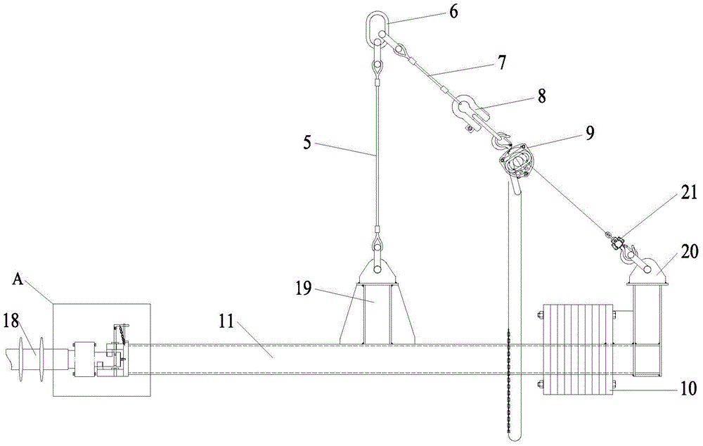
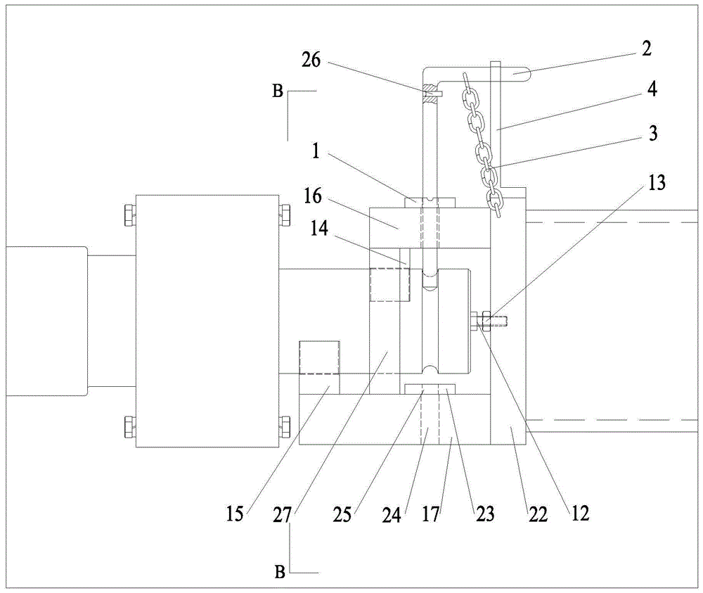
[0024] Such as figure 1 A novel extrusion roller changing device shown includes a shaft head fixing mechanism, a hoisting beam 11 and a drag mechanism driven by a crane, and the shaft head fixing mechanism is fixedly installed on one end of the hoisting beam 11 ( figure 1 middle left end), the other end of the hoisting beam 11 is provided with a counterweight 10; the middle part of the hoisting beam 11 is provided with a first hoisting platform 19, and the counterweight end of the hoisting beam 11 is also provided with a second hoisting platform 20; the drag mechanism It includes the suspension ring 6 that needs to be hung on the crown block when changing the roll, as well as the shackle 8 and the hook 21. The suspension ring 6 is connected to the shackle 8 through a short steel wire rope 7, ...


PUM


Abstract

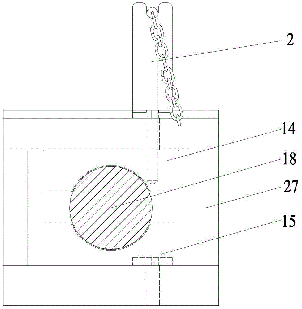
The invention discloses a novel wringing roller changing device. The novel wringing roller changing device comprises a shaft head fixing mechanism, a hoisting beam and a dragging mechanism driven by a crown block, wherein the shaft head fixing mechanism is fixedly installed on one end of the hoisting beam, and the other end of the hoisting beam is provided with a balancing weight; the dragging end of the dragging mechanism is connected with the hoisting beam; the shaft head fixing mechanism comprises a control rod, an upper clamping mold, a lower clamping mold, an upper clamping mold base and a lower clamping mold base, wherein the upper clamping mold base and the lower clamping mold base are arranged in parallel vertically; one ends of the upper clamping mold base and the lower clamping mold base are fixed on a support; the free end of the lower clamping mold base extends out of the edge of the free end of the upper clamping mold base; the lower surface of the free end of the upper clamping mold base is fixedly connected with the upper clamping mold which is provided with a semi-circular groove; the semi-circular groove is matched with the outer periphery surface of a shaft head of a wringing roller; the upper surface of the free end of the lower clamping mold base is fixedly connected with the lower clamping mold which is provided with another semi-circular groove; the another semi-circular groove is matched with the outer periphery surface of the shaft head of the wringing roller. According to the device, the roller changing efficiency is improved, and labor and material resources are saved.

Description

technical field [0001] The invention relates to the field of steel rolling machinery, in particular to a novel squeeze roll changing device. Background technique [0002] Squeeze rolls are important equipment for pickling strip steel in cold rolling mills. In cold rolling mills, it is necessary to replace worn and scratched squeeze rolls. The existing roll changing device is usually in the form of a full-circle sleeve. When changing the roll, first align the shaft head of the squeeze roller with the full-circle sleeve and insert it, and fix the shaft head of the squeeze roll with a set bolt. The reducer is used to adjust the position of the counterweight to change the center of gravity of the roller changing device to achieve balance, and finally the squeeze roller is pulled out. However, the roll changing device in the form of a full-circle sleeve requires multiple manual adjustments to insert the shaft head into the sleeve, and the set bolts only support a point on the ou...

Claims


Application Information

Patent Timeline
Patent Type & Authority Applications(China)
IPC IPC(8): B66C1/10B23P19/00
CPCB66C1/10B66C11/00
Inventor 徐蕾况群意
Owner WISDRI ENG & RES INC LTD
Learn More