Valve Timing Adjusting Apparatus
A technology for adjusting equipment and valve timing. It is used in mechanical equipment, timing lubrication, and controlling the pressure of lubricants. It can solve problems such as reduced rotational phase retention performance and reduced operating speed of vane rotors.
- Summary
- Abstract
- Description
- Claims
- Application Information
AI Technical Summary
Problems solved by technology
Method used
Image
Examples
no. 1 example
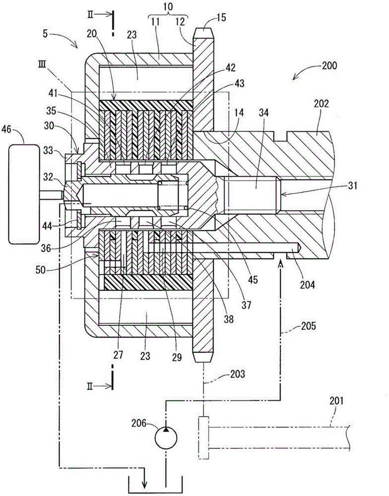
[0035] figure 1 A valve timing adjusting device according to a first embodiment of the present disclosure is shown. The valve timing adjusting device 5 adjusts the valve timing of an intake valve (not shown), which is driven to open and close by a camshaft 202 . Specifically, the valve timing adjusting device 5 adjusts the valve timing of the intake valve by rotating the camshaft 202 relative to the crankshaft 201 of the internal combustion engine 200 . The valve timing adjusting device 5 is placed in a driving force transmission path for transmitting driving force from a crankshaft 201 to a camshaft 202 of the internal combustion engine 200 . The crankshaft 201 serves as a driving side shaft of the present disclosure, and the camshaft 202 serves as a driven side shaft.
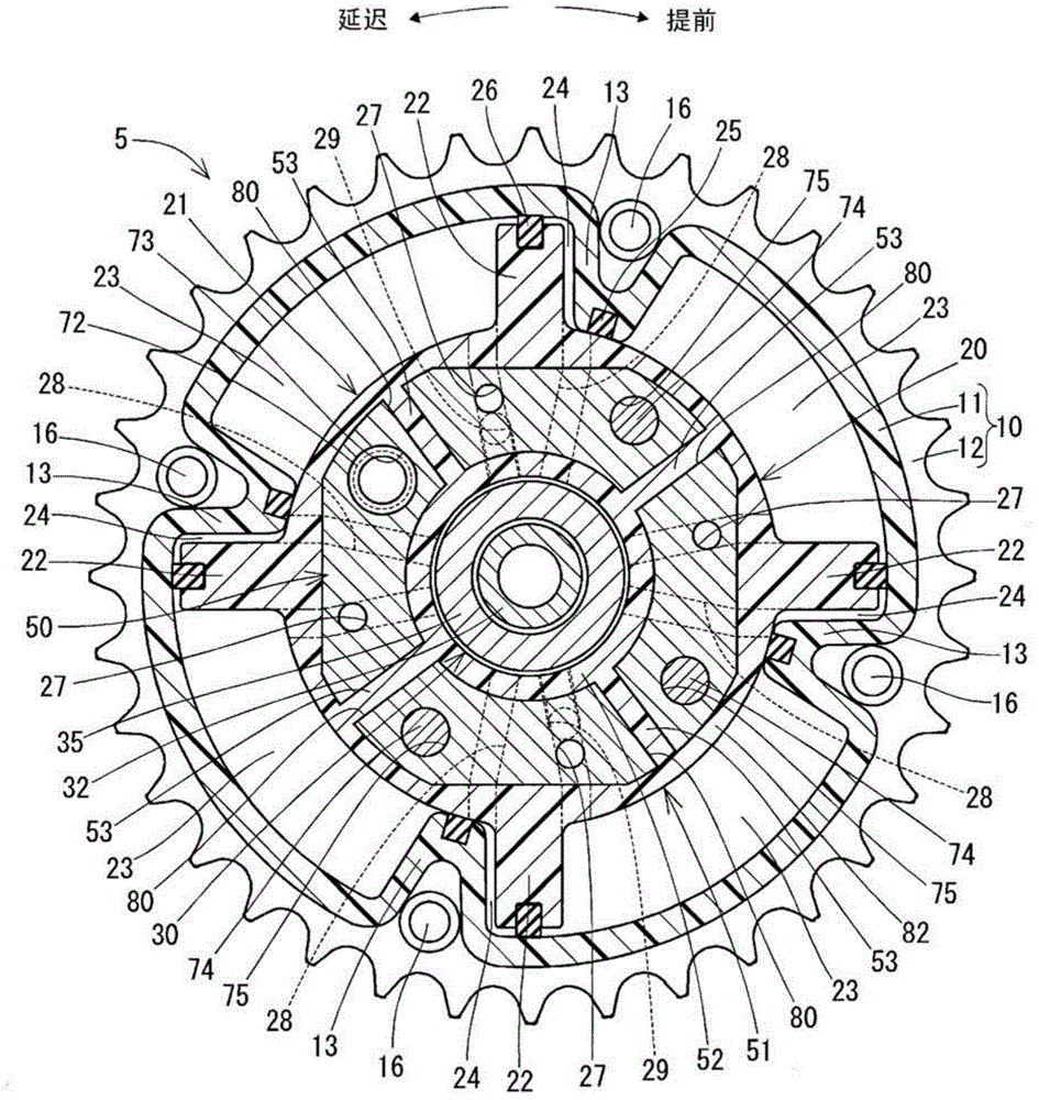
[0036] First, refer to figure 1 and 2 The entire structure of the valve timing adjusting device 5 is described.
[0037] Such as figure 1 and 2 As shown in , the valve timing adjustment device 5 includ...
no. 2 example
[0085] will refer to Figure 4-5 , 7-8, 10-11, and 14-24 describe a valve timing adjusting device according to a second embodiment of the present disclosure.
[0086] Such as Figures 14 to 16 As shown in , in the valve timing adjusting device 100 of the present embodiment, the vane rotor 101 includes a laminated portion 102 , a molded portion 51 , a sealing portion 103 and a connecting portion 104 .
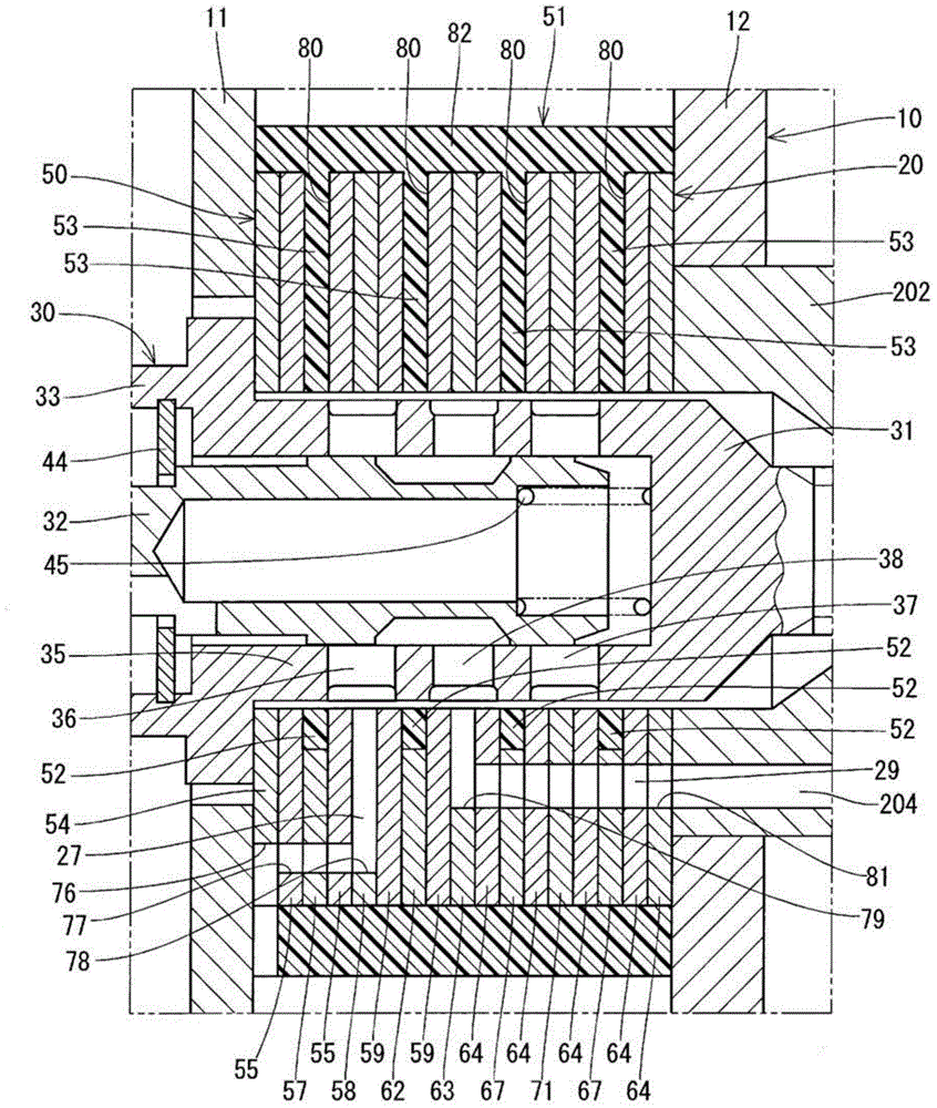
[0087] Such as Figure 16 As shown in, the laminated section 102 includes Figure 4 The metal plate 54 shown in, Figure 17 The metal plate 105 shown in, Figure 18 The metal plate 106 shown in, Figure 5 The metal plate 55 shown in, Figure 7 The metal plate 58 shown in, Figure 19 The metal plate 107 shown in, Figure 20 The metal plate 108 shown in, Figure 8 The metal plate 59 shown in, Figure 10 The metal plate 63 shown in, Figure 21 The metal plate 109 shown in, Figure 22 The metal plate 111 shown in, Figure 23 The metal plate 112 shown in, Figure 24 Met...
no. 3 example
[0107] will refer to Figure 25 A valve timing adjusting device according to a third embodiment of the present disclosure is described.
[0108] Such as Figure 25 As shown in , the valve timing adjusting device 130 of this embodiment includes a vane rotor 131 , a laminated portion 132 , a molded portion 51 and a sealing portion 133 .
[0109] The laminated portion 132 includes: the metal plate 54; the metal plate 55; the metal plate 106 and the sealing portion 133 (more specifically, a set of the metal plate 106 and the sealing portion 133 arranged along a common plane); the metal plate 55; the metal plate 58 metal plate 59; metal plate 108 and sealing portion 133 (more specifically, a set of metal plate 108 and sealing portion 133 arranged along a common plane); metal plate 59; metal plate 63; metal plate 64, metal plate 111 and sealing portion 133 (more specifically, a group of metal plates 111 and sealing portion 133 arranged along a common plane); metal plate 64; metal ...
PUM
 Abstract
Description
Claims
Application Information
 - R&D
- Intellectual Property
- Life Sciences
- Materials
- Tech Scout
- Unparalleled Data Quality
- Higher Quality Content
- 60% Fewer Hallucinations
Browse by: Latest US Patents, China's latest patents, Technical Efficacy Thesaurus, Application Domain, Technology Topic, Popular Technical Reports.
© 2025 PatSnap. All rights reserved.Legal|Privacy policy|Modern Slavery Act Transparency Statement|Sitemap|About US| Contact US: help@patsnap.com


