A heat pump-driven multi-stage solution dehumidification fresh air treatment unit

A fresh air treatment unit and solution dehumidification technology, which is applied in the directions of air treatment details, space heating and ventilation, space heating and ventilation details, etc., can solve the problems of lack of heat pump-driven solution dehumidification devices, etc., to improve inconsistent needs and meet Effect of heat demand, enhanced dehumidification capacity

Active Publication Date: 2017-09-26
TSINGHUA UNIV +1
View PDF3 Cites 0 Cited by
  • Summary
  • Abstract
  • Description
  • Claims
  • Application Information

AI Technical Summary

Problems solved by technology

[0005] Therefore, from the background of the prior art, there is still a lack of a heat pump-driven solution dehumidifier that can use all the heat on the condenser side to regenerate the solution.

Method used


Image

  • A heat pump-driven multi-stage solution dehumidification fresh air treatment unit
  • A heat pump-driven multi-stage solution dehumidification fresh air treatment unit

Examples


Embodiment 1

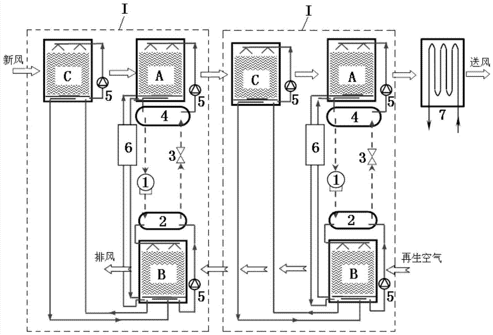
[0017] Such as figure 1 As shown, the fresh air treatment unit of the present embodiment includes a multi-stage fresh air treatment unit 1, and each fresh air treatment unit 1 includes a solution dehumidifier A, a solution regenerator B, an auxiliary solution dehumidifier C, and a compressor 1 , a condenser 2, an expansion valve 3 and an evaporator 4. Among them, the compressor 1, the condenser 2, the expansion valve 3 and the evaporator 4 are sequentially connected to form a solution heat exchange circulation circuit (also known as a heat pump circulation circuit); the heat exchange end of the condenser 2 is regenerated with the solution through a solution circulation pump 5 The solution circulation loop is formed by connecting the device B; the heat exchange end of the evaporator 4 is connected with the solution dehumidifier A through a solution circulation pump 5 to form a solution circulation loop; the auxiliary solution dehumidifier C is connected with a solution circulat...

Embodiment 2

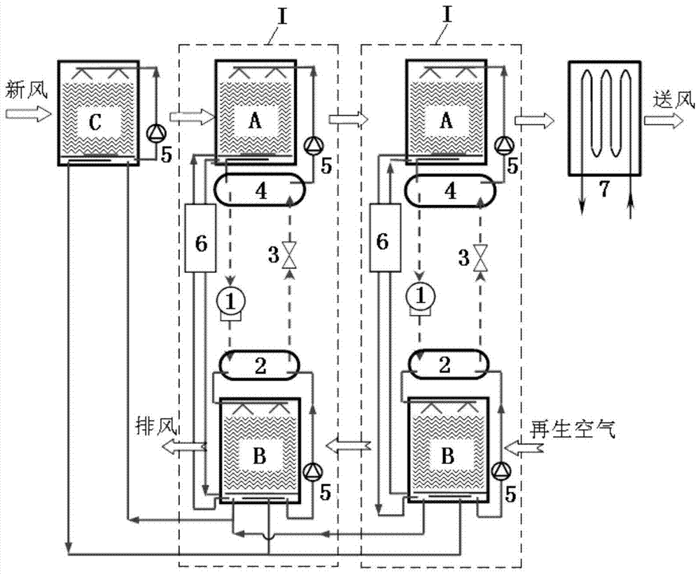
[0029] Such as figure 2 As shown, the difference between this embodiment and Embodiment 1 is that no auxiliary solution dehumidifier C is provided in the fresh air treatment units at all levels, and only one auxiliary solution dehumidifier C is provided in the whole fresh air treatment unit. In front of the solution dehumidifier A of the first-stage fresh air processing unit I, the auxiliary solution dehumidifier C and the solution circulation pump 5 are connected to form a solution circulation loop in the dehumidifier, and the auxiliary solution dehumidifier C is regenerated with the solutions of the fresh air processing units I at all levels Device B is connected to form a solution circulation loop.

[0030] The working principle of the fresh air treatment unit of this embodiment (the fresh air treatment unit including two-stage fresh air treatment unit 1 is used as an example to illustrate this embodiment), only differs in the setting of the auxiliary solution dehumidifier...


PUM


Abstract

The invention relates to a heat pump-driven multistage solution dehumidification fresh air processing set, comprising multiple stages of fresh air processing units; each stage of fresh air processing unit comprises a solution dehumidifier, a solution generator, an auxiliary solution dehumidifier, a compressor, a condenser, an expansion valve and an evaporator; the compressor, the condenser, the expansion valve and the evaporator of each unit are connected in sequence to form a solution heat exchange circulation loop; a heat exchange end of each condenser is connected with the corresponding solution generator by a solution circulating pump to form a solution circulation loop; a heat exchange end of each evaporator is connected with the corresponding solution dehumidifier by a solution circulating pump to form a solution circulation loop; each auxiliary solution dehumidifier is connected with a solution circulating pump to form an in-dehumidifier solution circulation loop; each solution generator is respectively connected with the corresponding solution dehumidifier and the corresponding auxiliary solution dehumidifier to form a solution circulating loop; the solution circulating loop between each solution generator and the corresponding solution dehumidifier is provided with a plate heat exchanger.

Description

technical field [0001] The invention relates to a fresh air treatment unit, in particular to a multi-stage solution dehumidification fresh air treatment unit driven by a heat pump. Background technique [0002] The main task of the building air-conditioning system is to meet the requirements of suitable indoor temperature and humidity parameters, and air dehumidification is an important link to meet the suitable indoor humidity level and improve the comfort of the indoor environment. Most of the existing dehumidification methods are condensation dehumidification methods, that is, low-temperature cold water, refrigerants and other refrigerants are used to cool the air below the dew point temperature, so that the moisture in the air condenses to complete the dehumidification process. Due to the low temperature of the cold source required (lower than the dew point temperature of the air), the evaporation temperature of the refrigerator is reduced, which seriously affects the co...

Claims


Application Information

Patent Timeline
Patent Type & Authority Patents(China)
IPC IPC(8): F24F3/14F24F12/00F24F13/30
CPCF24F3/14F24F12/00F24F13/30F24F2203/021
Inventor 刘晓华张涛陈晓阳
Owner TSINGHUA UNIV
Why Eureka
Try Eureka