
Chemiluminescence immunity analyzer incubator

A chemiluminescent immunoassay and incubator technology, applied in the field of medical devices, can solve the problems of reducing detection and analysis efficiency and contaminating samples, and achieve the effects of ensuring washing effect, improving efficiency, and simplifying structure

Active Publication Date: 2015-05-27
CHONGQING KEYSMILE BIOLOGICAL TECH CO LTD
View PDF6 Cites 3 Cited by
  • Summary
  • Abstract
  • Description
  • Claims
  • Application Information

AI Technical Summary

Problems solved by technology

[0003] When using the automatic chemiluminescence immunoassay analyzer, the medical unit will use the cuvette to contain the blood, and set the micropores on the inner wall of the cuvette. The traditional cuvette is a whole plate type, and its specification is generally 8×12 One, the corresponding reaction cup placement device is also a plate structure, and the plate type reaction cup placement device is placed on the mounting seat as a whole. When performing detection and analysis every time, it is necessary to take the entire plate of reaction cups and add them to the reaction cups. After blood and reaction reagents, it enters the incubation system for reaction. At present, the sample system, incubation system and detection system of most chemiluminescence immunoassay analyzers are limited by the structure, and each system operates independently. The transfer between the various systems is carried out manually, which will not only reduce the efficiency of detection and analysis, but also may contaminate the sample. When the researchers were studying the analyzer, they integrated the various systems of the analyzer and developed a New chemiluminescence immunoassay analyzer, which uses strip-shaped reaction cup strips for automatic transfer between systems, the incubation part of the new analyzer is combined with washing detection, and the transfer and delivery process of samples between various systems Automate

Method used


Image

  • Chemiluminescence immunity analyzer incubator
  • Chemiluminescence immunity analyzer incubator
  • Chemiluminescence immunity analyzer incubator

Examples


Embodiment Construction

[0031] The present invention will be further described below with reference to the embodiments and accompanying drawings.

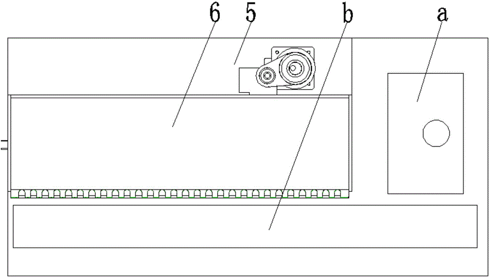
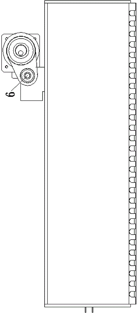
[0032] like Figure 1 to Figure 7 As shown, a chemiluminescence immunoassay incubator includes a box body 1, the box body 1 is mounted on a base 5, a linear slide rail is arranged on the base 5, and the lower surface of the bottom plate of the box body 1 is mounted on On the linear slide rail, an installation shaft is arranged on the box body 1, a first bearing 8 is sleeved on the installation shaft, and the inner ring of the first bearing 8 is fixedly sleeved on the installation shaft. The outer ring of the first bearing 8 is fixedly connected with the outer ring of the second bearing 9, the end face of the first bearing 8 is parallel to the end face of the second bearing 9, and the inner ring of the second bearing 9 is fixedly sleeved on the eccentric shaft, The eccentric shaft is driven by a motor.

[0033] One side of the box body 1 is open, and a plu...


PUM

PropertyMeasurementUnit
thermal conductivityaaaaaaaaaa

Abstract

The invention discloses a chemiluminescence immunity analyzer incubator which comprises a box body, wherein an opening is formed in the side face of the box body; a plurality of parallel partition boards are arranged on the upper surface of a base plate of the box body; the partition boards are perpendicular with the base plate of the box body; a reaction cup base mounting groove is formed between every two adjacent partition boards; and one end of the reaction cup base mounting groove is communicated with the opening in the side face of the box body. The incubator disclosed by the invention has significant effects that strip-shaped reaction cup strips are placed stably, and blood and reaction reagents in reaction cups can react rapidly and sufficiently by maintaining temperature inside the incubator to be constant and by shaking the box body, so that detection and analysis results are accurate and reliable; and the incubator can wash and inject a substrate timely, so as to improve the accuracy of the detection result and increase detection and analysis efficiency.

Description

technical field [0001] The invention belongs to the field of medical devices, in particular to an incubator for a chemiluminescence immunoassay analyzer. Background technique [0002] The fully automatic chemiluminescence immunoassay analyzer is a medical testing instrument that conducts immunoassays on the human body by detecting the serum of patients. Quantitative patient serum and reaction reagents are added to a white opaque microplate with antigen or antibody coated on solid phase, and the conjugate of the molecule to be tested in serum and horseradish peroxidase and the antigen or antigen on the solid phase carrier. The antibody specifically binds, and the unreacted free components are separated and washed; then, the luminescent primer is added, and the free energy released by the chemical reaction is used to excite the intermediate, returning from the ground state to the excited state, and the energy is released in the form of photons; The orifice plate is placed in ...

Claims


Application Information

Patent Timeline
Patent Type & Authority Applications(China)
IPC IPC(8): G01N35/02
Inventor 余农
Owner CHONGQING KEYSMILE BIOLOGICAL TECH CO LTD
Learn More