Electro-wetting display panel, manufacturing method of electro-wetting display panel and electro-wetting display device

An electrowetting display and panel technology, applied in optical elements, optics, instruments, etc., can solve the problems of complex structure and process, and achieve the effect of simplifying the process and structure, no viewing angle problem, and high color brightness.

Inactive Publication Date: 2015-05-27
BOE TECH GRP CO LTD
View PDF6 Cites 11 Cited by
  • Summary
  • Abstract
  • Description
  • Claims
  • Application Information

AI Technical Summary

Problems solved by technology

Existing electrowetting display panels must use a color filter layer to achieve color display, and the structure and process are relatively complicated

Method used


Image

  • Electro-wetting display panel, manufacturing method of electro-wetting display panel and electro-wetting display device
  • Electro-wetting display panel, manufacturing method of electro-wetting display panel and electro-wetting display device
  • Electro-wetting display panel, manufacturing method of electro-wetting display panel and electro-wetting display device

Examples


Embodiment Construction

[0036] The following will clearly and completely describe the technical solutions in the embodiments of the present invention with reference to the accompanying drawings in the embodiments of the present invention. Obviously, the described embodiments are only some, not all, embodiments of the present invention. Based on the embodiments of the present invention, all other embodiments obtained by persons of ordinary skill in the art without making creative efforts belong to the protection scope of the present invention.

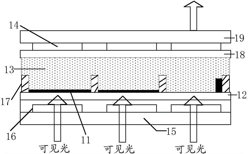
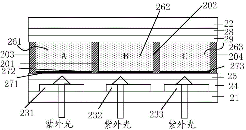
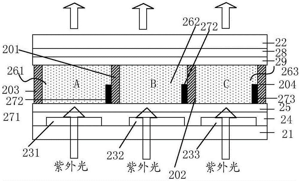
[0037] The electrowetting display panel according to the embodiment of the present invention includes a first substrate and a second substrate arranged opposite to each other; the electrowetting display panel further includes:

[0038] a dielectric layer disposed on the first substrate;

[0039] A plurality of sub-pixel unit delimiting regions disposed between the dielectric layer and the second substrate corresponding to the sub-pixel unit; the plurality of s...


PUM


Abstract

The invention provides an electro-wetting display panel, a manufacturing method of the electro-wetting display panel and an electro-wetting display device. The electro-wetting display panel comprises a first substrate, a second substrate, a dielectric layer, a plurality of sub pixel unit definition regions, first liquid and second liquid, wherein the first substrate and the second substrate are fastened together; the dielectric layer is arranged on the first substrate; the sub pixel unit definition regions are arranged between the dielectric layer and the second substrate, correspond to sub pixel units and isolated from one another; the first liquid and the second liquid are accommodated in the sub pixel unit definition regions; the first liquid can emit color light under the irradiation of excitation light; the second liquid can absorb the excitation light; when no electric filed is applied, the affinity of the dielectric layer to the second liquid is greater than that of the dielectric layer to the first liquid; and under the action of an electric filed, the affinity of the dielectric layer to the second liquid is less than that of the dielectric layer to the first liquid. The electro-wetting display panel can realize color display under the premise of not adopting a color layer.

Description

technical field [0001] The present invention relates to the field of display technology, in particular to an electrowetting display panel, a manufacturing method and an electrowetting display device. Background technique [0002] Electrowetting display is a technology that uses a "spread-shrink" behavior of non-polar liquids on hydrophobic dielectric films to achieve display effects. The operating principle is that when no voltage is applied to the component, the affinity of non-polar oil droplets to the hydrophobic dielectric layer (ie, the hydrophobic layer) is greater than that of the polar aqueous solution, so that the oil droplets are spread on the surface of the hydrophobic dielectric layer. When a voltage is applied to the device, the resulting charge distribution on the hydrophobic dielectric layer increases its affinity for water, driving oil droplets to be squeezed to the corners of the pixels. [0003] Fluorescence is a kind of cold luminescence phenomenon of pho...

Claims


Application Information

Patent Timeline
Patent Type & Authority Applications(China)
IPC IPC(8): G02B26/02
Inventor 赵伟利
Owner BOE TECH GRP CO LTD
Why Eureka
Try Eureka