
Broadband differential band-pass filter based on cross resonator

A bandpass filter and resonator technology, applied in waveguide devices, circuits, electrical components, etc., can solve the problems of wideband differential bandpass filters that have not yet been found, and achieve high differential mode passband selectivity and low insertion loss , low-cost effect

Inactive Publication Date: 2015-05-27
NANJING UNIV OF SCI & TECH
View PDF5 Cites 11 Cited by
  • Summary
  • Abstract
  • Description
  • Claims
  • Application Information

AI Technical Summary

Benefits of technology

This patented new design allows for better performance at different frequencies by generating multiple modes or zeros that are more sensitive than others. It also improves impedance match between signal lines without adding extra material like metal plating on them. Additionally, this design provides stable operation over time even when exposed to harsh environments such as extreme temperatures. Overall, these technical improvements improve electronic devices' ability to transmit signals effectively while maintaining their functionality.

Problems solved by technology

This patented describes various types of microwaves filters that can improve system's overall capabilities such as reducing interference between different modes or improving reception by specific frequency bands. These filters use thin metal plates called conductors for transmitting electromagnetic waves through which electric currents flow when excited. However, these conventional designs require long periods before being able to produce them accurately enough. To address this problem, there was developed a new type of device known as a Crossed Type Difference Band Pass Filter (CDF). CBF includes two layers: one layer consists mainly of copper plate made up of tiny circular openings filled with air; another layer contains fine wire patterns arranged perpendicularly across it. When placed next to each other, both layers form a complete circuit where current flows freely without any resistance.

Method used


Image

  • Broadband differential band-pass filter based on cross resonator
  • Broadband differential band-pass filter based on cross resonator
  • Broadband differential band-pass filter based on cross resonator

Examples


Embodiment Construction

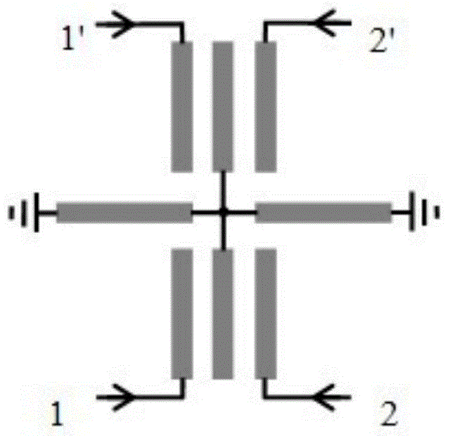
[0015] The present invention discloses a wideband differential bandpass filter based on a cross-shaped resonator, which includes a cross-shaped resonator. The four microstrip lines of the cross-shaped resonator are respectively the first microstrip line 3 and the second microstrip line in a clockwise direction. The microstrip line 4, the third microstrip line 5, and the fourth microstrip line 6, the first microstrip line 3 is located at the far right, and the first microstrip line 3 and the third microstrip line 5 are symmetrical about the y-axis, The second microstrip line 4 and the fourth microstrip line 6 are symmetric about the x-axis, and the first microstrip line 3 is provided with a first metallized through hole V 1 , The end of the third microstrip line 5 is provided with a second metallized through hole V 2 , The first microstrip line 3 and the second microstrip line 4 are simultaneously coupled with the fifth microstrip line 8, the second microstrip line 4 and the third...


PUM


Abstract

The invention discloses a broadband differential band-pass filter based on cross resonator which comprises a cross resonator, two metalized through holes at the tail ends of two stub lines of the resonator, four coupling structures, two input ends and two output ends. A microstrip line design of distribution parameters is adopted. The filter disclosed by the invention has the advantages of light weight, high reliability, excellent performance, good temperature stability, low production cost on a large scale and the like, and is particularly suitable for communication of corresponding microwave frequency bands, digital radar, single pawn satellite movement, military and civil multimode and multipath communication system terminals, wireless communication handheld terminals and the like, as well as corresponding systems which put strict requirements on weight, performance and reliability.

Description


Claims


Application Information

Patent Timeline
Owner NANJING UNIV OF SCI & TECH
Learn More