Thermal image arranging device, recording device, arranging system as well as thermal image arranging method and recording method
What is AI technical title?
AI technical title is built by Patsnap AI team. It summarizes the technical point description of the patent document.
A sorting device and recording technology, applied to measuring devices, TV system components, image communication, etc., can solve problems such as heavy workload and error-prone
Pending Publication Date: 2015-05-27
MISSION INFRARED ELECTRO OPTICS TECH
View PDF11 Cites 3 Cited by
Summary
Abstract
Description
Claims
Application Information
AI Technical Summary
This helps you quickly interpret patents by identifying the three key elements:
Problems solved by technology
Method used
Benefits of technology
Problems solved by technology
[0003] In various industries, the use of thermal imagers is becoming more and more popular, and they are used very frequently. For example, for the power industry, a 220KV substation may have about 500 frames of thermal image data; The thermal image data and other methods are sorted out, the workload is huge, and it is very easy to make mistakes
Method used
Image
Click on the blue label to locate the original text in one second.
Reading with bidirectional positioning of images and text.
Examples
Embodiment 1
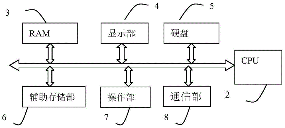
[0038] Example 1, figure 1 It is a block diagram of the electrical structure of the thermal image finishing device 1 of the present invention.
[0039] The thermal image organizing device 1 of this embodiment has a CPU2 for overall control, a RAM3 connected to the CPU2 via a bus, a display part 4, a hard disk 5, an auxiliary storage part 6, an operation part 7 and a communication part 8.
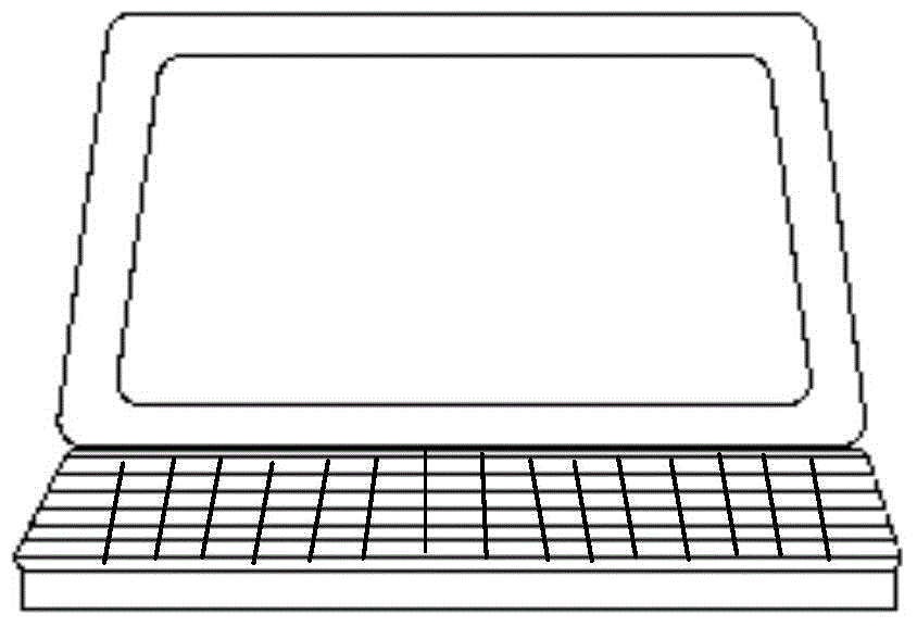
[0040] see figure 2 The external view of the thermal image organizing device 1 is shown. The thermal image organizing device 1 can be a computer, a PDA, a dedicated display processing device or a dedicated thermal image organizing device 1 .
[0041] RAM3 temporarily stores various data temporarily generated by CPU2 executing programs.
[0042] The display unit 4 is, for example, a liquid crystal display, and performs display under the control of the CPU 2 . Not limited thereto, the display unit 4 may also be another display connected to the image processing device 1 , and the image proc...
Embodiment 2
[0095] Embodiment 2 takes a portable thermal imaging device 13 with a shooting function as an example of a recording device. refer to Image 6 The structure of the thermal imaging device 13 of the second embodiment will be described.
[0096] The thermal imaging device 13 has a photographing part 1, an image processing part 2, a display and control part 3, a display part 4, a communication I / F5, a temporary storage part 6, a memory card I / F7, a memory card 8, a flash memory 9, an operation part 10, The control unit 11 is responsible for overall control of the thermal imaging device 13 by connecting the control and data bus 12 with the above corresponding parts.
[0097] The imaging unit 1 is composed of unillustrated optical components, lens driving components, infrared detectors, signal preprocessing circuits, and the like. The optics consist of an infrared optical lens for focusing the received infrared radiation onto the infrared detector. The lens driving part drives th...
PUM
Abstract
The thermal image processing apparatus and recording apparatus, processingsystem, and thermal image processing method and recording method of the present invention relate to the applied field of infrared detection. The workload of thermal image processing in the prior art is heavy. The thermal image processing apparatus of the present invention comprises: a selection part, used for selecting infrared data; a parsing part, used for parsing filmed object information associated with the selected infrared data; a comparison part, used for matching the filmed object information with filmed object data information stored in a storage medium; a recording part, used for, on the basis of infrared data corresponding to the filmed object information matched with the filmed object data information, making associative records of the filmed object data information with data acquired from processing the infrared data and / or the specifications thereof. A large amount of thermal image files can be quickly processed, resolving the problem of the prior art.
Description
technical field [0001] The thermal image sorting device, recording device, sorting system, thermal image sorting method, and recording method of the present invention relate to the application field of infrared detection. Background technique [0002] At present, the thermal image files captured by the thermal imaging device are generated according to the time or serial number of the file name; for the finishing work of the thermal image files obtained by shooting, one way is to make a thermal image file report. In the report, the subject information related to the photographed subject is manually entered and stored in the folder. Another way is to store in the infrared spectrum database of the thermal image file, in which multiple pieces of subject data information related to the subject are pre-stored, when the user selects a piece of subject data from the display interface After information, you can select the thermal image file corresponding to the object data informati...
Claims
Application Information
Patent Timeline
Application Date:The date an application was filed.
Publication Date:The date a patent or application was officially published.
First Publication Date:The earliest publication date of a patent with the same application number.
Issue Date:Publication date of the patent grant document.
PCT Entry Date:The Entry date of PCT National Phase.
Estimated Expiry Date:The statutory expiry date of a patent right according to the Patent Law, and it is the longest term of protection that the patent right can achieve without the termination of the patent right due to other reasons(Term extension factor has been taken into account ).
Invalid Date:Actual expiry date is based on effective date or publication date of legal transaction data of invalid patent.

