Supercharge Your Innovation With Domain-Expert AI Agents!

Cooling element

A technology for cooling components and electrical components, used in electrical components, cooling/ventilation/heating transformation, semiconductor devices, etc., can solve the problems of difficulty in ensuring sufficient cooling of electrical components and insufficient cooling performance, and achieve the effect of improving cooling capacity

Active Publication Date: 2015-05-27
ABB (SCHWEIZ) AG
View PDF6 Cites 8 Cited by
  • Summary
  • Abstract
  • Description
  • Claims
  • Application Information

AI Technical Summary

Problems solved by technology

[0004] The disadvantage of this cooling element is the insufficient cooling performance
Difficult to ensure adequate cooling of electrical components especially when used in conjunction with power semiconductor modules which generate a large thermal load during use

Method used


Image

  • Cooling element
  • Cooling element
  • Cooling element

Examples


Embodiment Construction

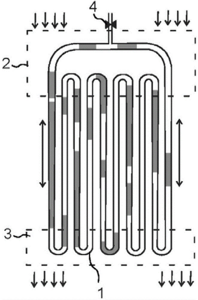
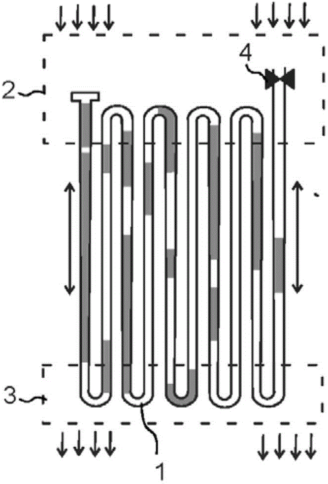
[0013] Figure 1a and Figure 1b The working principle of a pulsating heat pipe (PHP) is shown. Figure 1a shows the closed loop PHP and Figure 1b An open loop PHP is shown.

[0014] The pulsating heat pipe contains a tortuous flow channel 1 with capillary dimensions, in other words, a sufficiently small cross-section such that capillary forces dominate gravity. A suitable fluid can be introduced into the flow channel 1 via the injection valve 4 . Thus, the fluid moves by pulsation caused by pressure instability. Oscillations are generated in the small channel loop due to bi-directional expansion of the steam inside the channel. During operation, liquid plugs and elongated vapor bubbles will oscillate between cold and hot regions due to hydrodynamic instability induced by the rapid expansion of gas bubbles confined in small channels, and thus provide little dependence on The fluid velocity due to gravity. This makes the pulsating heat pipe rather insensitive to orientati...


PUM


Abstract

The invention relates to a cooling element (40) comprising a first surface (11) for receiving an electric component (12), a second surface (13) which is provided with fins (14) for forwarding a heat load received from the electric component (12) via the first surface (11) to surroundings. In order to obtain a cooling element providing efficient cooling one or more of the fins (14) are provided with a flow channel (1) for passing a fluid within each respective fin.

Description

technical field [0001] The invention relates to a cooling element and more precisely to a cooling element for cooling electrical components. Background technique [0002] Currently, cooling elements having a first surface for receiving electrical components are known. The second surface of the cooling element is provided with fins for transferring the heat load received from the electrical component via the first surface via the fins into the surrounding environment. [0003] Cooling elements of this type are usually installed in a horizontal orientation, but other orientations are also possible. Horizontal orientation refers to the orientation when the first surface faces upwards while the cooling fins protrude downwards. In that case, the channels for the air flow may be positioned between the fins, in other words below the electrical components attached to the first surface. [0004] A disadvantage of such cooling elements is the insufficient cooling performance. Espe...

Claims


Application Information

Patent Timeline
Patent Type & Authority Applications(China)
IPC IPC(8): H05K7/20
CPCF28D15/0266F28D2021/0029H01L23/427H01L23/467H01L2924/0002H01L2924/00
Inventor 托马斯·格拉丁格尔布鲁诺·阿戈斯蒂尼
Owner ABB (SCHWEIZ) AG
Features
  • R&D
  • Intellectual Property
  • Life Sciences
  • Materials
  • Tech Scout
  • Unparalleled Data Quality
  • Higher Quality Content
  • 60% Fewer Hallucinations
Learn More