Pump blade for submersible pump and submersible pump with same

A submersible pump and vane technology, which is applied to the components, pumps, pump devices and other directions of pumping devices for elastic fluids, can solve problems such as the existence of limitations in the settings, the inability to offset the load, and the reduction of radial loads, so as to reduce losses, The effect of shortening the length of the flow path and reducing noise

Active Publication Date: 2017-11-28
EBARA CORP
View PDF1 Cites 0 Cited by
  • Summary
  • Abstract
  • Description
  • Claims
  • Application Information

AI Technical Summary

Problems solved by technology

However, even with this setup, there are limits to the setup itself
This is because the sewage and sewage flow through the helical flow path of the pump blade, and the weight of the sewage and sewage itself will be loaded on the pump blade, so the radial load accompanying the rotation will change, so it is calculated by using clean water out mass will not be able to offset the load
Furthermore, even if the weight of sewage and sewage itself is considered in advance, the mixing ratio of sewage and sewage flowing in real time is constantly changing, so it is impossible to eliminate or reduce the radial load only by conventional pump blades with a single spiral flow path

Method used


Image

  • Pump blade for submersible pump and submersible pump with same
  • Pump blade for submersible pump and submersible pump with same
  • Pump blade for submersible pump and submersible pump with same

Examples


Embodiment Construction

[0045] Next, a pump blade according to an embodiment of the present invention will be described with reference to FIGS. 1 to 8 .

[0046] [the whole frame]

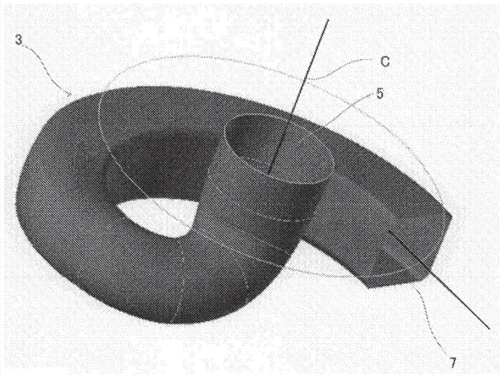
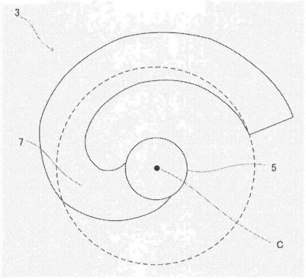
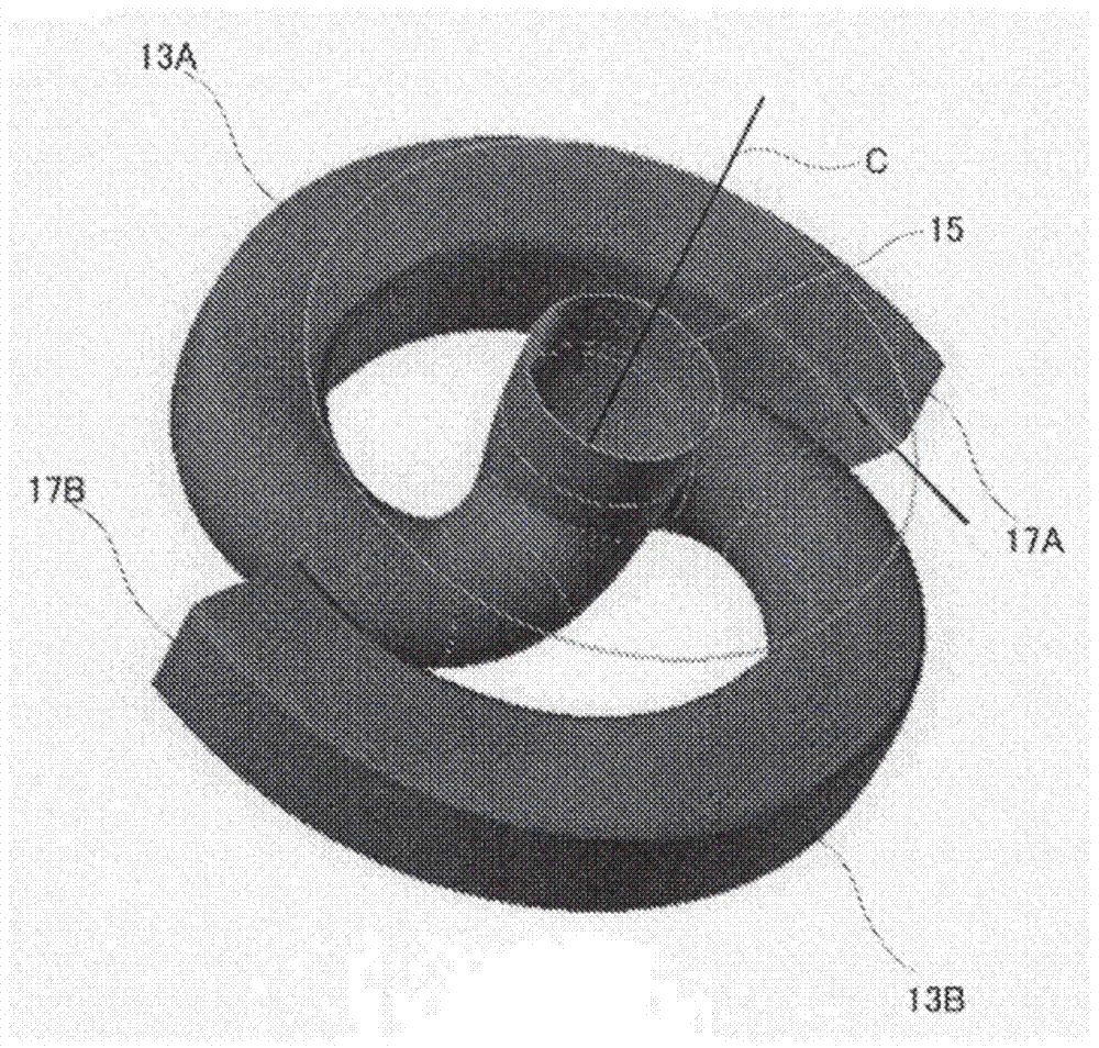
[0047] The pump vane of this embodiment has a plurality of flow paths communicating with the suction port coaxial with the rotation axis and the discharge port on the outer periphery, and the flow paths are logically arranged at equal angular intervals with respect to the rotation axis. Although the number of flow paths is not particularly limited, the cases shown in FIGS. 3 to 5 are embodiments in which there are two flow paths, and the cases shown in FIGS. 6 to 8 are embodiments in which there are three flow paths. The flow path is curved in a curved shape between the suction port and the discharge port. This pump vane can be manufactured by casting as an example. However, other metallic or non-metallic materials may be used as long as strength and corrosion resistance can be ensured.

[0048] [flow path]

[0049] F...


PUM


Abstract

The present invention provides a pump blade for a submersible pump and a submersible pump having the pump blade. Provides pump blades for submersible pumps that eliminate or reduce radial loads. The pump blade is a pump blade for a non-clogging submersible pump, and has: a substantially cylindrical main body; a suction port provided in the center of the lower end surface of the main body; a discharge port opened on the side of the main body; and The inside of the main body part is connected to a plurality of flow paths from the suction port to the discharge port, and the size, shape, and position of the flow paths are set to reduce fluid imbalance with respect to the axis of rotation. .

Description

technical field [0001] The present invention relates to a pump blade for a submersible pump, in particular to a pump blade for a submersible pump used in sewage and sewage and a submersible pump with the pump blade. Background technique [0002] In the past, as submersible pumps for sewage and sewage, there were Figure 10 structure shown. In this submersible pump, the internal Figure 9 The pump vane 111 shown (refer to patent document 1). The pump vane 111 is a substantially cylindrical pump vane 111 with a suction port 129 formed at one end and a discharge port 134 formed at the side of the other end, and a helical spiral connecting the suction port 129 and the discharge port 134 is formed inside. Shaped flow path 135. Further, the discharge port 134 protrudes outward from the suction port side portion along the peripheral surface of the pump vane 111 and has a flange portion 140 that separates the suction port side from the discharge port side. [0003] The pump vane...

Claims


Application Information

Patent Timeline
Patent Type & Authority Patents(China)
IPC IPC(8): F04D7/04F04D29/22
CPCF04D7/04F04D29/225F04D29/2255F04D29/669F04D13/02F04D29/426
Inventor 川井政人坂顶浩美大渕真志打田博矶野美帆
Owner EBARA CORP
Why Eureka
Try Eureka