A desorption tower and its heating gas inlet channel

A technology for heating gas and air intake channels, which is applied to the separation of dispersed particles, chemical instruments and methods, and separation methods. It can solve problems such as uneven flow rates of heating gas, and achieve the effects of reducing technical costs and avoiding technical risks.

Active Publication Date: 2017-07-25
ZHONGYE-CHANGTIAN INT ENG CO LTD
View PDF6 Cites 0 Cited by
  • Summary
  • Abstract
  • Description
  • Claims
  • Application Information

AI Technical Summary

Problems solved by technology

[0008] The technical problem to be solved in the present invention is how to propose a high-temperature pipeline distribution technology that is closer to the wall of the desorption tower, and overcome the problem of uneven flow velocity of the heating gas existing on the flow direction section based on this technology

Method used


Image

  • A desorption tower and its heating gas inlet channel
  • A desorption tower and its heating gas inlet channel
  • A desorption tower and its heating gas inlet channel

Examples


Embodiment 1

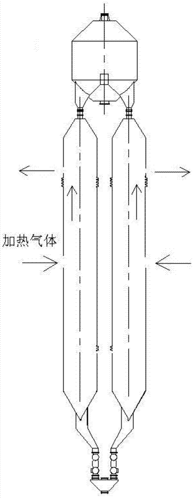
[0037] See diagram 2-1 , which is a schematic diagram of the overall structure of the analytical tower device described in this embodiment.

[0038] The analysis tower device includes two analysis tower main bodies, so as to control the safety height of the tower body on the basis of satisfying the system analysis capability. The activated carbon that has completed the adsorption enters the heat exchange tubes in the main bodies of the two desorption towers through the silo. In the main bodies of the two desorption towers, the heat exchange tubes are heated by the heating gas, thereby indirectly heating the activated carbon in the desorption towers. The activated carbon is in the high temperature zone (320 -490℃) for a certain period of time, so that the adsorbed SO 2 When harmful substances are decomposed and discharged at high temperature, the adsorption function of activated carbon can be restored and the regeneration of activated carbon can be realized; the activated car...

Embodiment 2

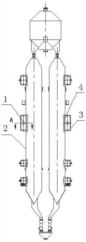
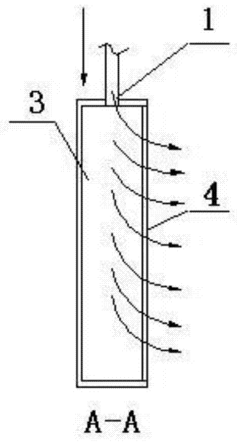
[0050] The schematic diagram of the overall structure of the analytical tower device described in this embodiment is as follows diagram 2-1 As shown, the difference from the first embodiment lies in the structure of the flow equalizer 4, corresponding to the situation where the heated gas enters the intake buffer chamber 3 in the horizontal direction, the flow balance plate 4 described in this embodiment is distributed with vertical installation In addition, in the air intake direction of the horizontal air inlet, the inclination angle of the louvers gradually increases from the middle to both ends, so that when the gas in the middle part with a fast circulation velocity passes through the louvers with a small inclination angle in the middle, the speed will be affected by a certain amount. However, when the gas at the two ends with a relatively slow flow velocity passes through the louvers with a large inclination angle, it can relatively maintain its original velocity. For de...


PUM


Abstract

The invention relates to the technical field of activated carbon desulfurization and denitrification, and provides a desorption tower and its heating gas inlet passage, including an inlet buffer chamber arranged between the inlet pipe and the tower wall; the inlet of the inlet buffer chamber Located on the outer wall directly connected to the tower wall of the air inlet buffer chamber; the air inlet buffer chamber is connected with the tower wall of the desorption tower through an equalizing plate, and the equalizing plate is on the air inlet direction of the air inlet The circulation capacity gradually increases from the center to both ends. Compared with the prior art, firstly, it avoids the problem of uneven flow rate caused by the sudden enlargement of the space when the heating gas directly enters the desorption tower from the intake pipe. Second, break the limitations of pipeline layout, reduce technical risks and technical costs. Further, the flow capacity of the equalizer plate in the air inlet direction increases gradually from the center to both ends, so as to avoid the adverse effects caused by the decreasing trend of the flow velocity of the heated gas in the direction of diffusion from the center to the outer ends.

Description

technical field [0001] The invention relates to the technical field of activated carbon desulfurization and denitrification, in particular to an activated carbon desulfurization and denitrification analysis tower and a heating gas inlet channel thereof. Background technique [0002] The adsorption tower and the desorption tower are the two main reaction places of activated carbon desulfurization and denitrification technology. The two organically cooperate to complete the adsorption of harmful substances in the exhaust flue gas, as well as the regeneration and activation of activated carbon; SO in 2 , NO X and other harmful gases. Therefore, on the basis of meeting the requirements of flue gas emission, high-concentration SO can be recycled. 2 , while realizing the recycling of activated carbon. [0003] As we all know, the regeneration and activation technology of activated carbon that has adsorbed harmful substances mainly includes two methods: dosing analysis and heati...

Claims


Application Information

Patent Timeline
Patent Type & Authority Patents(China)
IPC IPC(8): B01D53/02
Inventor 傅旭明肖中元
Owner ZHONGYE-CHANGTIAN INT ENG CO LTD
Why Eureka
Try Eureka