Low-slitter-edge radius tool

A technology of corner cutter and edge circle, applied in metal processing and other directions, can solve the problems of not satisfying product appearance, use safety, material waste, etc., and achieve the effect of saving strip bag materials, simplifying processing procedures, and ensuring the effect of slitting.

Active Publication Date: 2015-06-03
JOYEA CORP
7 Cites 1 Cited by

AI-Extracted Technical Summary

Problems solved by technology

[0002] Strip bag product packaging equipment needs to cut continuous strip bag products through cutting molds. If ordinary cutting molds are used for cutting, the corners of the cut ends can only form right angles, which cannot meet the requirements of product beauty and safety in use. higher requirements
Chinese patent CN 202781311U discloses a strip bag cutting mold, whi...

Abstract

The invention relates to a low-slitter-edge radius tool used for cutting continuous strip bag products. The low-slitter-edge radius tool comprises a male mold and a female mold which can move relatively front and back; the female mold is formed by a fixed female mold and a movable female mold; the movable female mold can move front and back relative to the fixed female mold; two sides of the movable female mold and the fixed female mold can be spliced to form a pair of integral female mold circular bead cutting edges; a pair of male mold circular bead cutting edges matched with the female mold circular bead cutting edges are formed on two sides of the rear part of the male mold; a transverse male mold cutting edge is arranged in the middle of the front part of the male mold; meanwhile, a female mold cutting edge is arranged on the fixed female mold of the female mold; when the movable female mold moves backwards, the female mold cutting edge can be exposed and is staggered with the male mold cutting edge to realize the cutting action of adjacent strip bags. The circular bead cutting and cutting of continuous strip bags are realized in one mold, the packaging efficiency is improved; meanwhile, a vertical slitter edge is avoided, so the waste of material is reduced.

Application Domain

Metal working apparatus

Technology Topic

RADIUSEdge matching +1

Image

  • Low-slitter-edge radius tool
  • Low-slitter-edge radius tool
  • Low-slitter-edge radius tool

Examples

  • Experimental program(1)

Example Embodiment

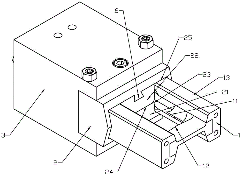
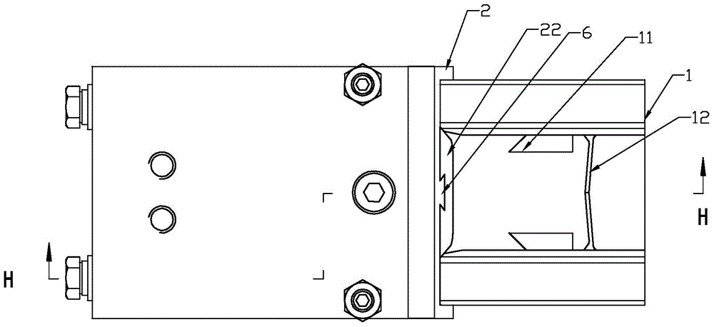
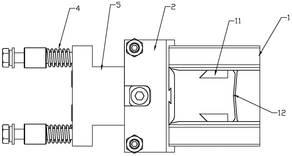
[0019] Such as figure 1 , figure 2 , Figure 4 As shown, the low waste round corner cutter includes a male mold 1 and a female mold 2 that can move relatively back and forth; the female mold is composed of a fixed female mold 21 and a movable female mold 22 that are aligned with each other. The fixed female mold 21 is fixedly installed on the mold base 3, and the movable female mold 22 can move back and forth relative to the fixed female mold 21; when the movable female mold is at the front limit position, both sides of the movable female mold 22 and the fixed female mold 21 Spliced ​​to form a complete female mold fillet cutting edge 23 (see Figure 7 ), both sides of the rear part of the male mold 1 have a pair of male mold fillet cutting edges 11 that are matched with the female mold fillet cutting edges 23 (see Image 6 ), so that when the male mold moves relative to the female mold, the rounded cutting edges of the male mold and the female mold can cut the corners of two adjacent strips to form rounded corners; the front middle position of the male mold 1 A transverse male mold cutting edge 12 is provided, and the fixed female mold 21 of the female mold 2 has a female mold cutting edge 24 matching the male mold cutting edge 12 on the front end of the mating surface of the movable female mold. When the movable female mold 22 moves backward, the cutting edge 24 of the female mold can be exposed and interlace with the cutting edge 12 of the male mold to complete the cutting action of adjacent strips.
[0020] Such as image 3 , Figure 5 As shown, a spring 4 capable of pushing the movable female mold to the front limit position is installed between the movable female mold 22 and the fixed mold base 3. Both sides of the male mold 1 and the female mold 2 are provided with mutually matched guide posts 13 and guide grooves 25 (see respectively Image 6 with Figure 7 ), the rear end of the guide column passes through the guide groove 25 and then abuts on a connecting block 5 connected to the rear end of the movable female mold 22 and can push the connecting block backward; the front end of the connecting block 5 is fixed by the female mold The fixed extension part is restricted, and the spring 4 is pressed between the rear end of the connecting block 5 and the fixed mold base 3. Before cutting, the movable female mold is pushed forward by the spring 4 to be level with the fixed female mold. When the male mold 1 enters the female mold, the male mold's rounded cutting edge 11 first and the female mold's rounded cutting edge 23 Cooperate, cut the corners of the two connected strip bags D to form rounded corners; then the male mold continues to move forward and then moves, and the connecting block 5 is pushed backward through the guide post 13 to drive the movable female mold 22 to move backward, exposing The female mold cutting edge 24, and then the male mold cutting edge 12 that moves backward and the female mold cutting edge 24 are staggered to cut the two connected strips. The shape of the two strip bags D2 after being cut is like Figure 8 As shown, only the corners have waste edges B2, but no longitudinal waste edges.
[0021] Such as Figure 7 As shown, the movable female mold 22 and the fixed female mold 21 have linear guide rails 6 that cooperate with each other.
[0022] Such as Figure 4 As shown, the connecting block 5 and the fixed mold base 3 are guided by a guide sleeve 51 and a guide rod 31 in cooperation.

PUM

no PUM

Description & Claims & Application Information

We can also present the details of the Description, Claims and Application information to help users get a comprehensive understanding of the technical details of the patent, such as background art, summary of invention, brief description of drawings, description of embodiments, and other original content. On the other hand, users can also determine the specific scope of protection of the technology through the list of claims; as well as understand the changes in the life cycle of the technology with the presentation of the patent timeline. Login to view more.

Similar technology patents

Paper cutting device of printer

ActiveCN103419229AImprove working abilityGuaranteed cutting effect
Owner:JIANGMEN DASCOM COMP PERIPHERAL

Anti-bonding rubber crushing device

InactiveCN112208032Aimprove qualityGuaranteed cutting effect
Owner:烟台海蝶玩具有限公司

Light harvesting cutter

InactiveCN102500935AIncrease the intensity of incoming lightGuaranteed cutting effect
Owner:夏致俊

Paper cutting device

PendingCN107363873AGuaranteed cutting effect
Owner:HENAN HUAGANG PRINTING

Pneumatic shearing machine

ActiveCN104139205AImprove cleanlinessGuaranteed cutting effect
Owner:江门市泽星钢结构工程有限公司

Classification and recommendation of technical efficacy words

  • Guaranteed cutting effect
  • Simplify processing

Paper tube cutting device

InactiveCN109227697AGuaranteed cutting effect
Owner:湖北恒鑫纸制品股份有限公司

Pneumatic shearing machine

ActiveCN104139205AImprove cleanlinessGuaranteed cutting effect
Owner:江门市泽星钢结构工程有限公司

Light harvesting cutter

InactiveCN102500935AIncrease the intensity of incoming lightGuaranteed cutting effect
Owner:夏致俊

Paper cutting device of printer

ActiveCN103419229AImprove working abilityGuaranteed cutting effect
Owner:JIANGMEN DASCOM COMP PERIPHERAL

Paper cutting device

PendingCN107363873AGuaranteed cutting effect
Owner:HENAN HUAGANG PRINTING

Automatic tee shaping equipment and shaping method thereof

InactiveCN102500710Ahigh degree of automationSimplify processing
Owner:珠海天达制冷设备有限公司

Disposable high-speed turbo dental-drill hand-device

InactiveCN101053533ASimplify processinglow cost
Owner:BEIJING NORTH POLE DENTAL HANDPIECE

Processing method for flexible-rigid board of high-pixel camera module

InactiveCN108289375AGood flatnessSimplify processing
Owner:SHENZHEN HUALIN CIRCUIT TECH

Preparation method of modified and micronized 2-mercaptopyridine oxide zinc salt

InactiveCN101862273Areduce adhesionSimplify processing
Owner:深圳市矽尔德新材料有限责任公司
Why Eureka
Try Eureka