Front traction device for low-speed motor tractor

A front traction and tractor technology, which is applied to traction connectors, vehicle components, transportation and packaging, etc., can solve the problems of small output and increase production costs, and achieve the effect of increasing costs, saving costs and realizing the traction function.

Inactive Publication Date: 2015-06-03
SINO TRUK JINAN POWER
View PDF6 Cites 0 Cited by
  • Summary
  • Abstract
  • Description
  • Claims
  • Application Information

AI Technical Summary

Problems solved by technology

At present, the structure of the front traction device of heavy-duty tractors is generally in the form of Y-shaped traction pin plus cast traction pin support. Due to the different layout and structure of the front end of the vehicle model, the structure of the type traction pin plus the casting traction pin support needs to be redesigned, which will greatly increase the production cost

Method used


Image

  • Front traction device for low-speed motor tractor
  • Front traction device for low-speed motor tractor
  • Front traction device for low-speed motor tractor

Examples


Embodiment Construction

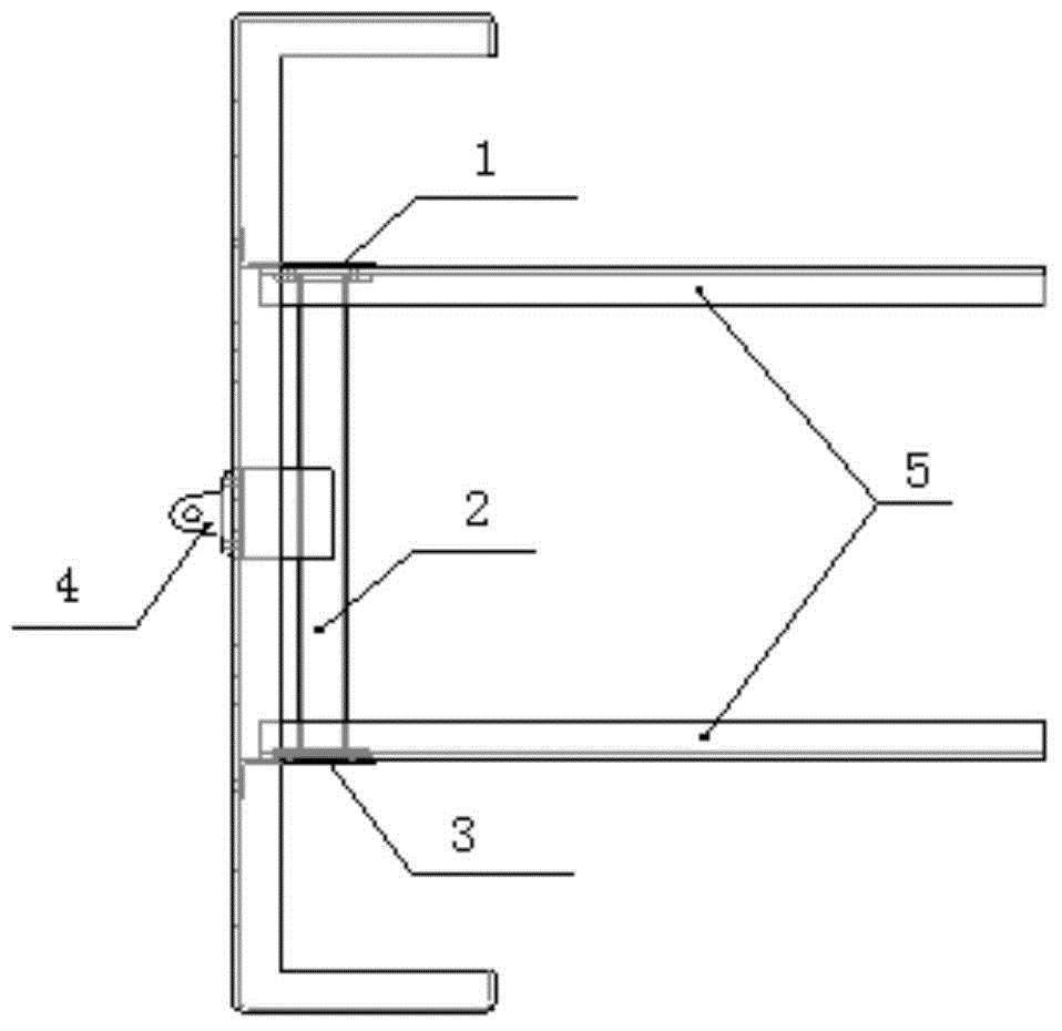
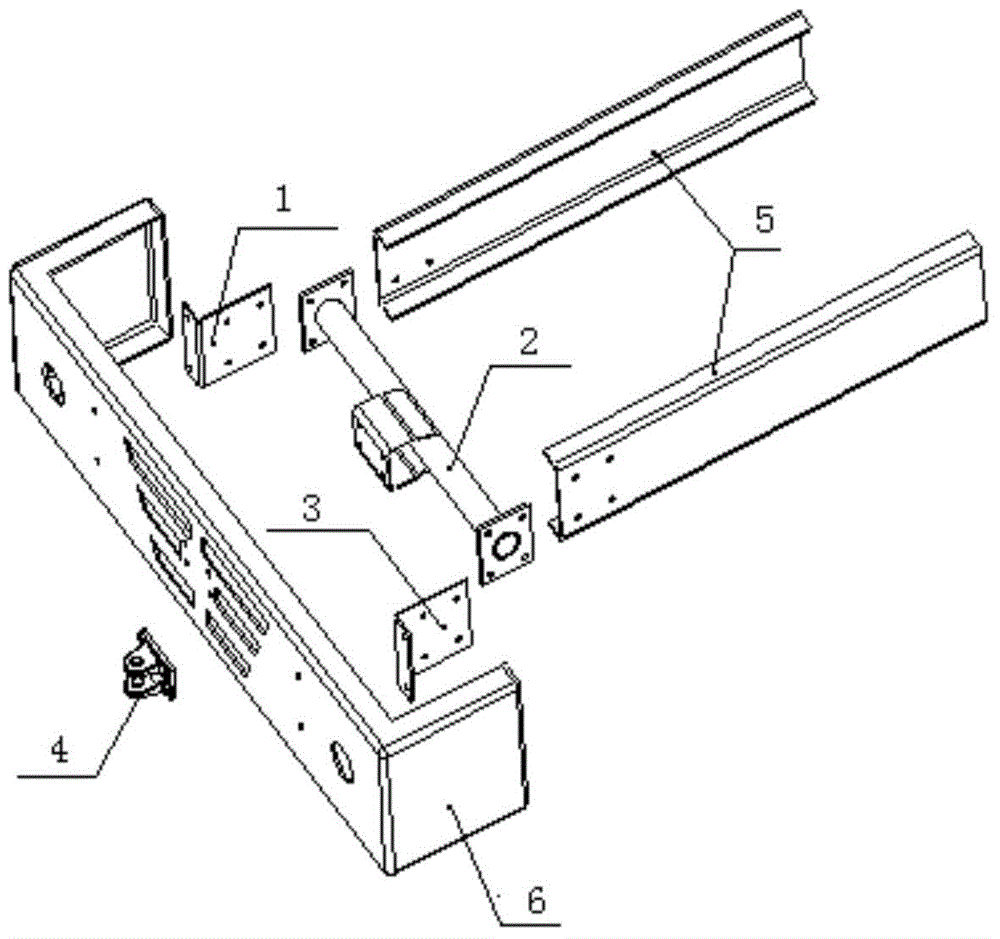
[0019] Depend on figure 1 with figure 2 It can be seen that a front traction device for a low-speed tractor includes a front traction lug assembly 4, a bumper 6, a fixed beam 2 and a vehicle frame assembly 5, wherein the front traction lug assembly 4 is installed on the bumper 6 At the front end, the fixed beam 2 is installed at the rear end of the bumper 6 , and the vehicle frame assembly 5 is installed at the rear end of the bumper 6 through the fixed beam 2 .

[0020] The front traction device also includes a bumper bracket assembly for fixing the fixed beam 2 and the vehicle frame assembly 5, and the bumper bracket assembly includes a first bumper bracket 1 and a first bumper bracket respectively located at the left and right ends of the fixed beam 2. Second bumper bracket 3. The first bumper bracket 1 and the second bumper bracket 3 are installed on the bumper 6 .

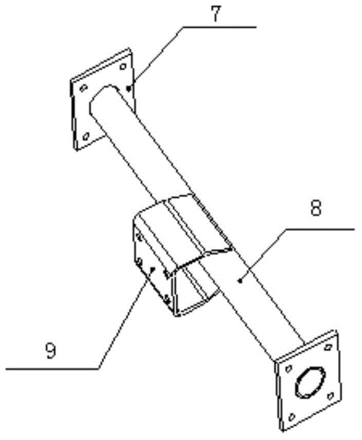
[0021] The fixed beam 2 includes a tubular beam 8 , a first support 7 and a second support located at t...


PUM


Abstract

The invention relates to a front traction device for a low-speed motor tractor. The front traction device comprises a front traction ear plug assembly, a bumper, a fixed beam and a frame assembly, wherein the front traction ear plug assembly is installed on the front end of the bumper, the fixed beam is installed on the rear end of the bumper, and the frame assembly is installed on the rear end of the bumper by virtue of the fixed beam. By adopting the front traction device, a solution for installing the front traction device is provided for a special vehicle model produced in a small batch. A mold is needed for producing a casting, the mold for a large-sized casting is expensive, if the yield is low, and the cost for a single unit is greatly increased. By adopting the front traction device, a novel mold is not needed, only the bumper needs to be correspondently changed, and a fixed beam which is simple in structure needs to be designed, so that not only is the cost saved, but also the traction function is realized.

Description

technical field [0001] The invention relates to a front traction device for heavy-duty vehicles, in particular to a front traction device for low-speed traction vehicles. Background technique [0002] General heavy-duty vehicles are equipped with front traction devices for self-rescue or other traction operations. At present, the structure of the front traction device of heavy-duty tractors is generally in the form of Y-shaped traction pin plus cast traction pin support. Due to the different layout and structure of the front end of the vehicle model, the structure of the type traction pin and the casting traction pin support needs to be redesigned, which will greatly increase the production cost. Contents of the invention [0003] The invention proposes a front traction device for a low-speed tractor, which forms a novel front traction device by improving the original bumper. [0004] For solving above technical problem, technical scheme of the present invention is as fo...

Claims


Application Information

Patent Timeline
Patent Type & Authority Applications(China)
IPC IPC(8): B60D1/14
Inventor 代伟亚于成超陈清旺
Owner SINO TRUK JINAN POWER
Why Eureka
Try Eureka