Method for making non-woven mesh composite non-woven fabric with rotary weft laying method
A non-woven fabric and rotary technology, applied in the direction of non-woven fabrics, textiles and papermaking, etc., can solve problems such as equipment vibration, uneven arrangement of warp and weft yarns, and reduction of product physical indicators
- Summary
- Abstract
- Description
- Claims
- Application Information
AI Technical Summary
Problems solved by technology
Method used
Image
Examples
Embodiment 1
[0097] Example 1 produces a square nonwoven mesh composite nonwoven fabric.
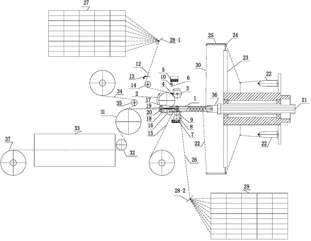
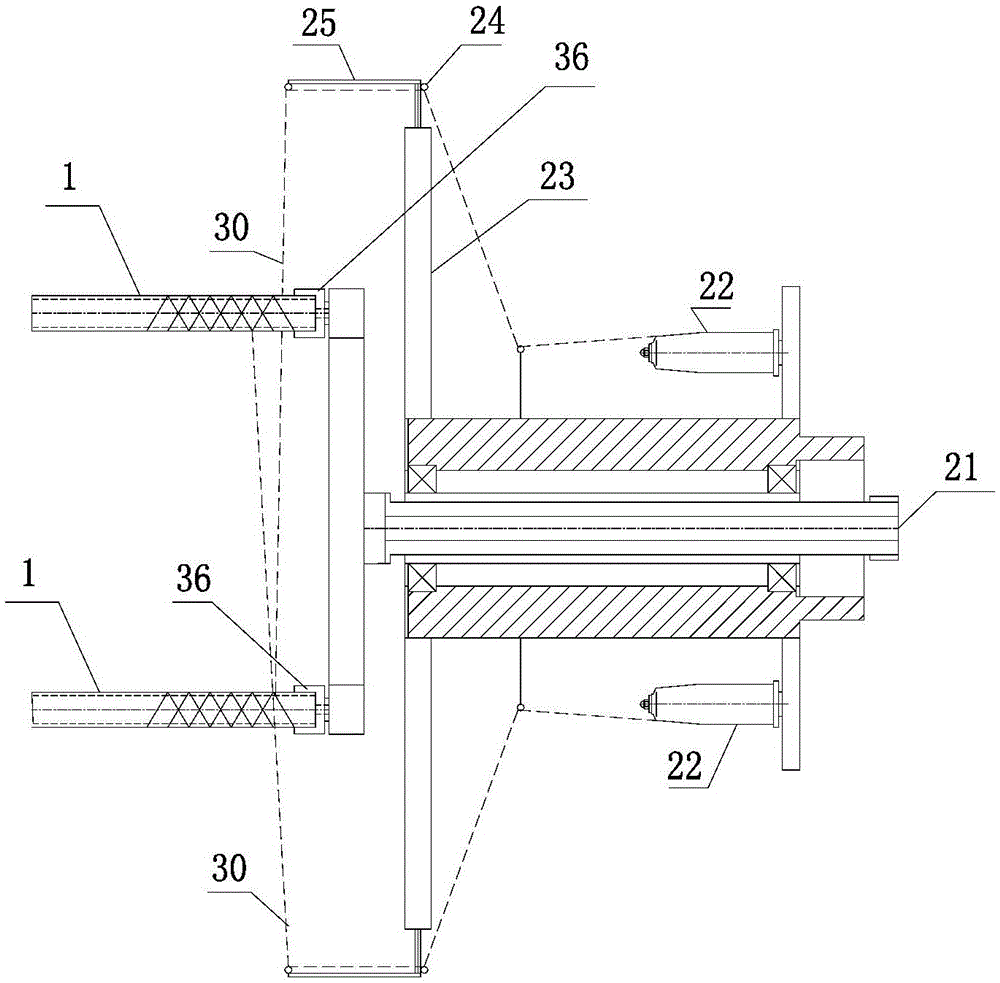
[0098] ① Use glass fiber as warp yarn (alkali-free 68Tex) and weft yarn (alkali-free 136Tex). The continuous fiber weft yarn 30 is continuously drawn out from the weft yarn head 22 by the rotation of the large rotating disk 23 of the rotary weft laying machine, and the weft yarn 30 is inserted into the rotating rotating screw by the yarn guide eye 24 and the yarn guide rod 25 In the spiral groove of 1, the weft yarn is evenly wound on the two rotating screws 1; the rotating screw 1 rotates evenly, and the arranged weft yarns move forward at a uniform speed.
[0099] The structure of the rotary weft laying machine includes a central shaft 21, a large rotating disk 23, a screw rotating head 36, a rotating screw 1, a yarn guide rod 25, a yarn guide eye 24, etc. The central shaft 21 is equipped with a large rotating disk 23, which rotates The turntable 23 rotates around the central axis 21, a plurality of we...
Embodiment 2
[0108] Example 2 produces a diamond-shaped nonwoven mesh composite nonwoven fabric.
[0109] ① Use glass fiber as warp yarn (alkali-free 68Tex) and weft yarn (alkali-free 68Tex). Continuous fiber weft yarns (also called diagonal ribs, because they do not form a 90° angle with the warp yarns) 30, through the rotation of the large rotating disk 23, the weft yarns are drawn out from the weft yarn head 22 without interruption, and the warp guide eyes 24, The guide rod 25 allows the weft yarn 30 to be inserted into the spiral groove of the rotating rotating screw 1 so that the weft yarn is wound on the left and right rotating screws 1 in a uniform diamond shape; the rotating screw 1 rotates evenly, and the arranged weft yarns move forward at a uniform speed.
[0110] The structure of the rotary weft laying machine includes a central shaft 21, a large rotating disk 23, a screw rotating head 36, a rotating screw 1, a yarn guide rod 25, a yarn guide eye 24, etc. The central shaft 21 is equ...
Embodiment 3
[0119] Example 3 Production of square nonwoven mesh composite nonwoven fabric
[0120] ① Use glass fiber as warp yarn (alkali-free 68Tex) and weft yarn (alkali-free 68Tex). Continuous fiber weft yarn 30, through the rotation of the large rotating disk 23 of the rotary weft laying machine, the weft yarn 30 is drawn out from the weft yarn head 22 without interruption, and the weft yarn is inserted into the rotating rotating screw by the yarn guide eye 24 and the yarn guide rod 25 In the screw groove of 1, the weft yarn is evenly wound on the left and right rotating screws 1; the rotating screw 1 rotates evenly, and the arranged weft yarns move forward at a uniform speed.
[0121] The structure of the rotary weft laying machine includes a central shaft 21, a large rotating disk 23, a screw rotating head 36, a rotating screw 1, a yarn guide rod 25, a yarn guide eye 24, etc. The central shaft 21 is equipped with a large rotating disk 23, which rotates The turntable 23 rotates around th...
PUM
 Abstract
Description
Claims
Application Information
 - R&D
- Intellectual Property
- Life Sciences
- Materials
- Tech Scout
- Unparalleled Data Quality
- Higher Quality Content
- 60% Fewer Hallucinations
Browse by: Latest US Patents, China's latest patents, Technical Efficacy Thesaurus, Application Domain, Technology Topic, Popular Technical Reports.
© 2025 PatSnap. All rights reserved.Legal|Privacy policy|Modern Slavery Act Transparency Statement|Sitemap|About US| Contact US: help@patsnap.com


