Railway isolation transformer

A technology for isolating transformers and railways, applied in the direction of transformers/inductor coils/windings/connections, etc., can solve the problem of high cost of transformers, achieve cost reduction, reduce copper loss, and shorten the effect of magnetic circuits

Inactive Publication Date: 2015-02-18
TIANJIN YUANHE HUATIE ELECTRICAL EQUIP
View PDF5 Cites 0 Cited by
  • Summary
  • Abstract
  • Description
  • Claims
  • Application Information

AI Technical Summary

Problems solved by technology

[0003] The invention aims to solve the above technical problems, and provides a new type of railway isolation transformer. In addition to solving the problem of high cost of the existing transformer, it can also effectively improve the heat dissipation effect. Compared with the transformer structure disclosed in the patent, it reduces the cost of the transformer. The effect of high is more obvious

Method used


Image

  • Railway isolation transformer

Examples


Embodiment Construction

[0010] Specific embodiments of the invention will be described in detail below in conjunction with the accompanying drawings.

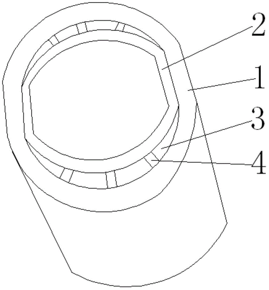
[0011] Such as figure 1 As shown, a railway isolation transformer structure includes a primary winding 1 and a secondary winding 2, the secondary winding 2 is wound outside the cylindrical core, the primary winding 1 is located outside the secondary winding 2, and the primary The winding 1 and the secondary winding 2 are both elliptical structures with straight sides on both sides, and an insulating layer is provided on the periphery of the primary winding 1 and the secondary winding 2. The straight sides of the primary winding 1 and the The length of the straight part of the secondary winding 2 is equal, and the insulating layer of the straight part of the primary winding 1 and the insulating layer of the straight part of the secondary winding 2 are connected to each other, and the length of the primary winding 1 is The axis is greater than the long...


PUM


Abstract

The invention provides a railway isolation transformer structure which comprises a primary winding and a secondary winding, wherein the primary winding is wound on the outer side of a cylindrical iron core; the primary winding is located on the outer side of the secondary winding; the primary winding and the secondary winding both have oval-shaped structures with straight edges on two sides; the length of a straight edge part of the primary winding is equal to the length of a straight edge part of the secondary winding; an insulating layer of the straight edge part of the primary winding is connected with an insulating layer of the straight edge part of the secondary winding; a long axis of the primary winding is greater than the long axis of the secondary winding; arc edge parts of the primary winding and arc edge parts of the secondary winding are formed into arc-shaped cavities; a plurality of reinforcing ribs are arranged in each arc-shaped cavity. According to the railway isolation transformer structure, the oval-shaped structures are adopted, and the whole height and width of the iron core are both less than the height and width of circular and square iron cores, so that the loss of the iron core is reduced, the center distance of the oval-shaped iron core is reduced, the magnetic circuit is shortened, the no-load current is correspondingly reduced, the total loss of the transformer is further reduced, and the running cost is reduced.

Description

technical field [0001] The invention belongs to the field of electric equipment, and in particular relates to a railway isolation transformer. Background technique [0002] At present, the iron cores used in traditional railway isolation transformers are generally fixed cylindrical iron cores or square iron cores. Although the iron cores with circular cross-section and rectangular cross-section are beautiful in appearance, they have relatively high core losses, large no-load current, and large total transformer loss, which increases production costs and reduces product profit margins. Chinese patent CN201522917 U discloses an elliptical oil-immersed distribution transformer, which includes a cylindrical core and low-voltage windings and high-voltage windings wound on the core. The winding is also set in this elliptical structure, and the low-voltage winding and the high-voltage winding are provided with insulating layers. Although the transformer disclosed in the patent so...

Claims


Application Information

Patent Timeline
Patent Type & Authority Applications(China)
IPC IPC(8): H01F27/28H01F27/32
Inventor 杨洪智
Owner TIANJIN YUANHE HUATIE ELECTRICAL EQUIP
Why Eureka
Try Eureka