Hinging type hydraulic pipe joint

A hydraulic pipe joint, articulated technology, applied in the direction of pipe/pipe joint/pipe fitting, elbow, siphon, etc., can solve the problem that the installation space pipe joint is difficult to meet the requirements, and achieves the elimination of matrix thread failure, small size and reliable sealing Effect

Active Publication Date: 2015-06-03
SHENYANG INST OF AUTOMATION - CHINESE ACAD OF SCI
View PDF7 Cites 0 Cited by
  • Summary
  • Abstract
  • Description
  • Claims
  • Application Information

AI Technical Summary

Problems solved by technology

Most of the existing pipe joints have certain limitations, which bring a lot of inconvenience in practical applications. For example, ordinary pipe joints are difficult to meet the requirements in the occasions where the installation space is small, the direction needs to be adjusted, frequent disassembly or internal wiring is required

Method used


Image

  • Hinging type hydraulic pipe joint
  • Hinging type hydraulic pipe joint
  • Hinging type hydraulic pipe joint

Examples


Embodiment 1

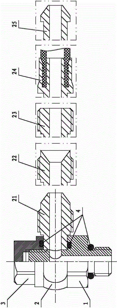
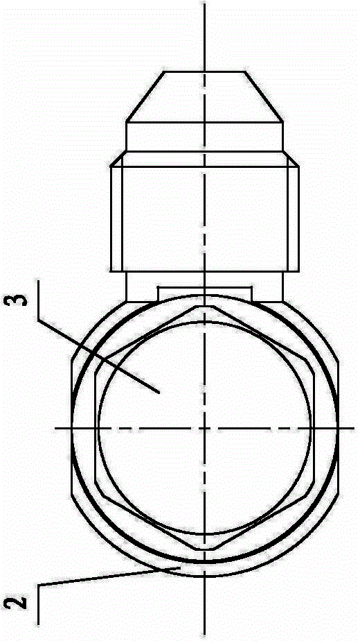
[0029] Such as figure 1 , figure 2 and Figure 6 As shown, the articulated pipe joint fixing base 1 of this embodiment is an ordinary articulated pipe joint fixing base 11, that is, one end of the ordinary articulated pipe joint fixing base 11 is threadedly connected to the substrate, and can be connected with the threaded hole of the substrate. Matching, thread optional models are pipe thread, M thread, pipe thread is preferred; the other end of the ordinary articulated pipe joint fixing base 11 is provided with an external thread (thread Optional models include pipe thread and M thread, pipe thread is preferred); there is a gap 14 between the other end of the common articulated pipe joint fixing base 11 and the articulated pipe joint lock nut 3 . Ordinary articulated pipe joint fixing base 11 is respectively provided with accommodation on the end surface in contact with articulated pipe joint steering joint 2 and the end surface of articulated pipe joint locking nut 3 in ...

Embodiment 2

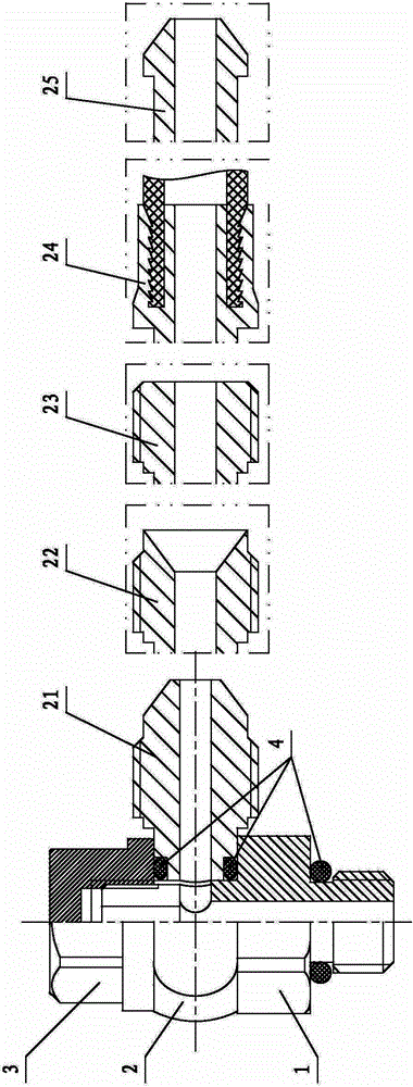
[0036] In order to meet the needs of installing data lines or other linear items inside the pipe joint, the hinged pipe joint fixing base 1 of this embodiment is a wire-type hinged pipe joint fixing base 12, such as image 3 , Figure 4 , Figure 5 and Figure 7 As shown, one end of the threaded hinged pipe joint fixing base 12 is threadedly connected to the substrate, which can be matched with the threaded hole of the substrate. The available thread types include pipe thread and M thread, and pipe thread is preferred; The other end of the articulated pipe joint fixing base 12 is provided with an external thread that is threadedly connected with the articulated pipe joint lock nut 3 (thread optional models include pipe thread and M thread, pipe thread is preferred); There is a gap 14 between the other end of the fixed base 12 of the type pipe joint and the locking nut 3 of the hinged pipe joint. The end face of the articulated pipe joint adjustment joint 2 in contact with t...


PUM


Abstract

The invention belongs to the hydraulic engineering field, in particular to a hinging type hydraulic pipe joint. The hinging pipe hydraulic pipe joint comprises a hinging type hydraulic pipe joint fixing base, a hinging type pipe joint steering joint and a hinging type pipe joint lock nut; one end of the hinging type pipe joint fixing base is installed on a base body of a hydraulic pipeline; the other end is in thread connection with the hinging type pipe joint lock nut; one end of the hinging type pipe joint steering joint sleeves the hinging type pipe joint fixing base and is respectively in sealing connection with the hinging type pipe joint fixing base and the hinging type pipe joint lock nut; positioning is achieved through the hinging type pipe joint lock nut; the other end of the hinging type pipe joint steering joint is provided with a steering joint which is connected with an external connection hydraulic pipeline; the hinging type pipe joint fixing base is respectively provided with an oil inlet hole and an oil outlet; the oil inlet hole is communicated with the steering joint through the oil outlet. The hinging pipe hydraulic pipe joint has the advantages of being compact in structure and steerable, allowing internal routing, being convenient to maintain and low in fault rate and the like.

Description

technical field [0001] The invention belongs to the field of hydraulic engineering, in particular to an articulated hydraulic pipe joint applied to the connection of hydraulic pipelines. Background technique [0002] At present, in the hydraulic system, the connecting parts of the hydraulic system are an indispensable and important part of the hydraulic system. Most of the existing pipe joints have certain limitations, which bring a lot of inconvenience in practical applications. For example, ordinary pipe joints are difficult to meet the requirements in the occasions where the installation space is small, direction adjustment is required, frequent disassembly or internal wiring is required. Contents of the invention [0003] In order to solve the above-mentioned problems existing in the existing pipe joints, the object of the present invention is to provide a hinged hydraulic pipe joint. The articulated hydraulic pipe joint can be widely used in the connection of hydraul...

Claims


Application Information

Patent Timeline
Patent Type & Authority Applications(China)
IPC IPC(8): F15B21/04F16L43/00
CPCF15B21/04F16L43/00
Inventor 霍良青张奇峰张竺英孙斌杜林森
Owner SHENYANG INST OF AUTOMATION - CHINESE ACAD OF SCI
Why Eureka
Try Eureka