Distributed optical fiber temperature monitoring system

A distributed optical fiber and monitoring system technology, applied in signal transmission systems, non-electrical signal transmission systems, instruments, etc., can solve the problem of increasing laying costs, involving monitoring areas and monitoring center master station networking, data transmission and reading The speed cannot be real-time and fast, etc., to achieve the effect of high precision, fast data transmission and reading speed

Active Publication Date: 2008-07-16
浙江振东光电科技有限公司
View PDF0 Cites 10 Cited by
  • Summary
  • Abstract
  • Description
  • Claims
  • Application Information

AI Technical Summary

Problems solved by technology

[0003] However, at present, the application of distributed optical fiber temperature sensing system is basically based on the stand-alone version of the independent application, and some of them are applied in the network environment, and also use the additional Ethernet to transmit data
In the practical application of the distributed optical fiber temperature sensing system, if it is necessary to detect the temperature of some sensitive areas in a large range, and it is necessary to summarize these detection results to the central control room, it is necessary to monitor each monitoring area distributed in the detection area. Regional nodes are controlled (such as setting collection time, collection parameters, etc.), because the entire detection area is generally large (generally within the range of 30km to 100km), a single distributed optical fiber temperature sensing system cannot meet the requirements, which is inevitable It involves the networking problem between the monitoring area and the monitoring center master station
[0004] The general method is to use an additional Ethernet network to complete the networking function, and use a star structure or a point-to-point mode to complete signal transmission, as shown in Figure 1. The implementation method is to pass temperature signals or other monitoring signals in the area to be monitored. The extra Ethernet is transmitted to the main station of the monitoring center. This kind of networking method not only requires additional laying of external networks, but also increases the cost of laying, and is not suitable for working in harmful environments such as high voltage and strong electromagnetic fields, and the data transmission and reading speed cannot be real-time. fast

Method used


Image

  • Distributed optical fiber temperature monitoring system
  • Distributed optical fiber temperature monitoring system

Examples


Embodiment Construction

[0018] The present invention will be further described in detail below with reference to the embodiments of the drawings.

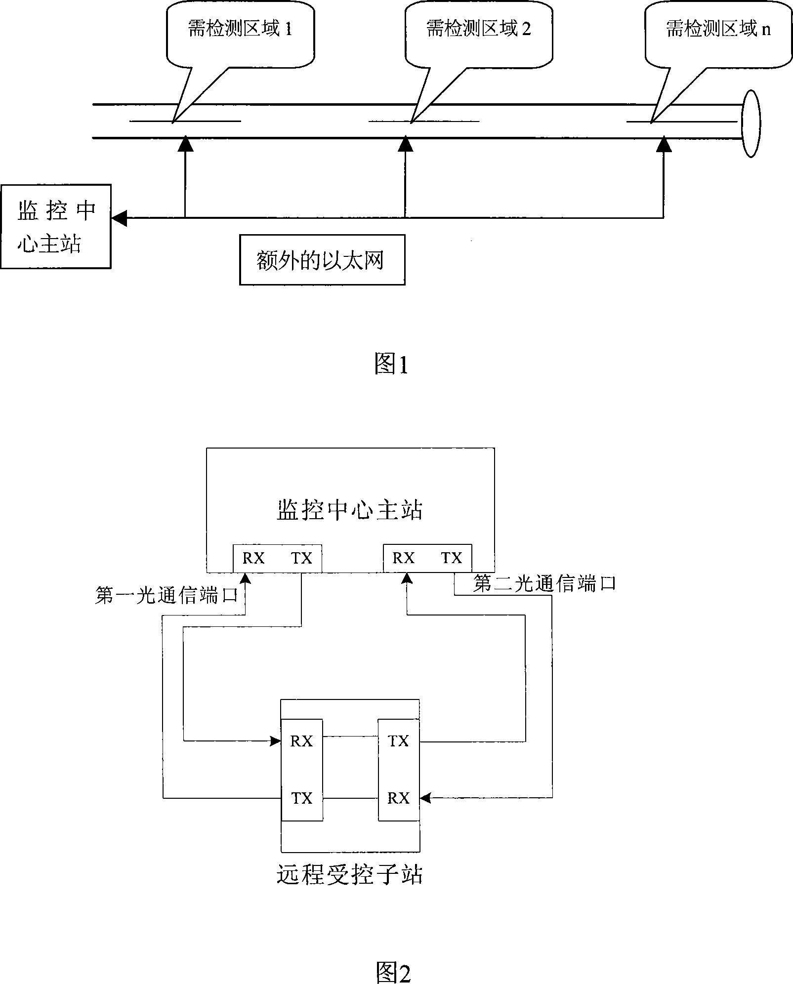
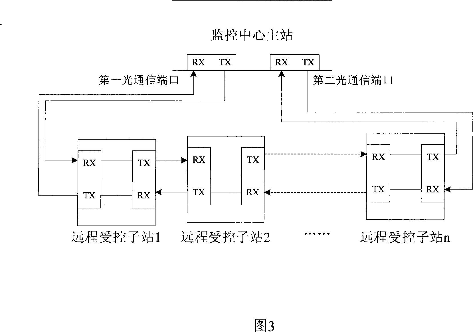
[0019] The present invention provides a distributed optical fiber temperature sensing system, which includes a monitoring center master station. The monitoring center master station includes at least two optical communication ports, at least one of which is connected to the monitoring center master station through an optical fiber and is The monitored remote controlled substation includes at least a temperature sensor module and at least two optical fiber transceivers. Of course, the remote controlled substation can also be equipped with other monitoring devices according to actual needs.

[0020] The electrical ports of the two optical fiber transceivers in the above remote controlled substation are both connected to the temperature sensor module, and the receiving end of the first optical fiber transceiver optical port is connected to the transmitting end o...


PUM


Abstract

The invention relates to a distribution type optical fiber temperature monitoring system, which comprises a monitoring center master station, and at least one remote controlled substation connected with the monitoring center master station through optical fiber, wherein the remote controlled substation at least comprises a temperature sensor module. The invention is characterized in that: the remote controlled substation at least comprises two optical fiber transceivers; the electric ports of the two optical fiber transceivers are both connected with the temperature sensor module; the optical port of a first optical fiber transceiver of a first remote controlled substation is connected with the first communication port of the monitoring center master station, the optical port of a second optical fiber transceiver of a last remote controlled substation is connected with the second communication port of the monitoring center master station, and each two adjacent remote controlled substations are connected through optical fiber. The invention does not need extra networking cost; signal transmission is sent to the monitoring center master station through a two-way loop, and when the optical fiber at one side of one remote controlled substation encounters abnormality, the signal is transmitted to the monitoring center master station through the optical fiber at the other side.

Description

Technical field [0001] The invention relates to a temperature monitoring system, in particular to a distributed optical fiber temperature monitoring system that needs to monitor a temperature area with a large range and the monitoring area is scattered. Background technique [0002] Distributed optical fiber temperature sensing system is a sensing system for real-time measurement of spatial temperature field distribution. This technology was first proposed by the University of Southampton in 1981, and products have been developed abroad (mainly in the UK, Japan and other countries). Domestic research is also being actively carried out in this area, and a series of distributed optical fiber temperature sensors have been successfully developed, and have been initially applied in some industrial fields. The distributed optical fiber temperature sensor (DTS) system is based on advanced optical time domain reflectance. The principle of (OTDR) technology and the temperature effect of t...

Claims


Application Information

Patent Timeline
Patent Type & Authority Applications(China)
IPC IPC(8): G08C23/06
Inventor 杨如祥
Owner 浙江振东光电科技有限公司
Why Eureka
Try Eureka