Supercharge Your Innovation With Domain-Expert AI Agents!

A planetary roller screw and method for uniform load distribution thereof

A planetary roller and screw technology, which is applied to transmissions, belts/chains/gears, mechanical equipment, etc., can solve the problems of demanding space and output force, small lead, and the end of meshing threads falling off.

Active Publication Date: 2019-10-18
BEIJING RES INST OF PRECISE MECHATRONICS CONTROLS +1
View PDF5 Cites 2 Cited by
  • Summary
  • Abstract
  • Description
  • Claims
  • Application Information

AI Technical Summary

Problems solved by technology

[0003] Due to the increasingly stringent requirements on the space occupied by electromechanical actuators and the output force, this requires that the roller screw as a key transmission component not only has a smaller lead, but also has a load capacity higher than the ordinary load index, so If the ordinary roller screw is used as the transmission part of the electromechanical actuator, it is very easy to cause the end of the meshing screw to fall off, which will lead to the failure of the transmission of the roller screw

Method used


Image

  • A planetary roller screw and method for uniform load distribution thereof
  • A planetary roller screw and method for uniform load distribution thereof
  • A planetary roller screw and method for uniform load distribution thereof

Examples


Embodiment 1

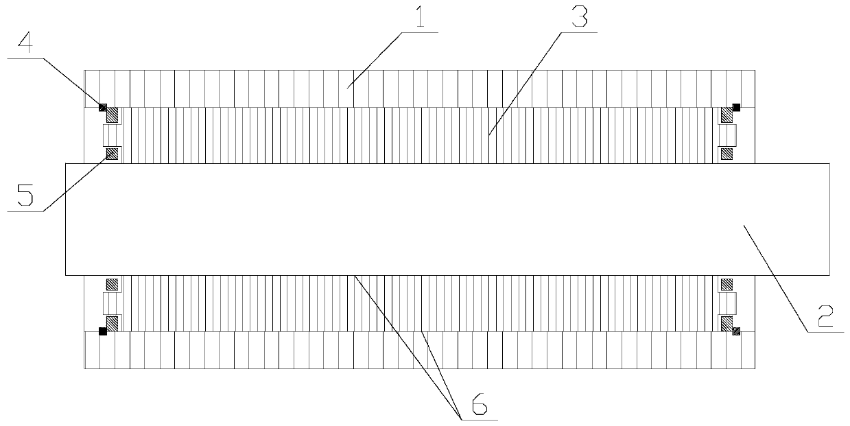
[0037] Such as figure 1 , Figure 6 as well as Figure 7 As shown, a planetary roller screw provided in this embodiment includes a screw 2, a nut 1, two retaining rings 4, two cages 5 and more than three rollers 3, and the screw 2 is located at Inside the nut 1 and coaxially arranged with the nut 1 , more than three rollers 3 are located between the screw 2 and the nut 1 and rotate relative to the screw 2 and the nut 1 . A retaining ring 4 and a cage 5 are located at the left end of the roller 3 , and another retaining ring 4 and another cage 5 are located at the right end of the roller 3 .

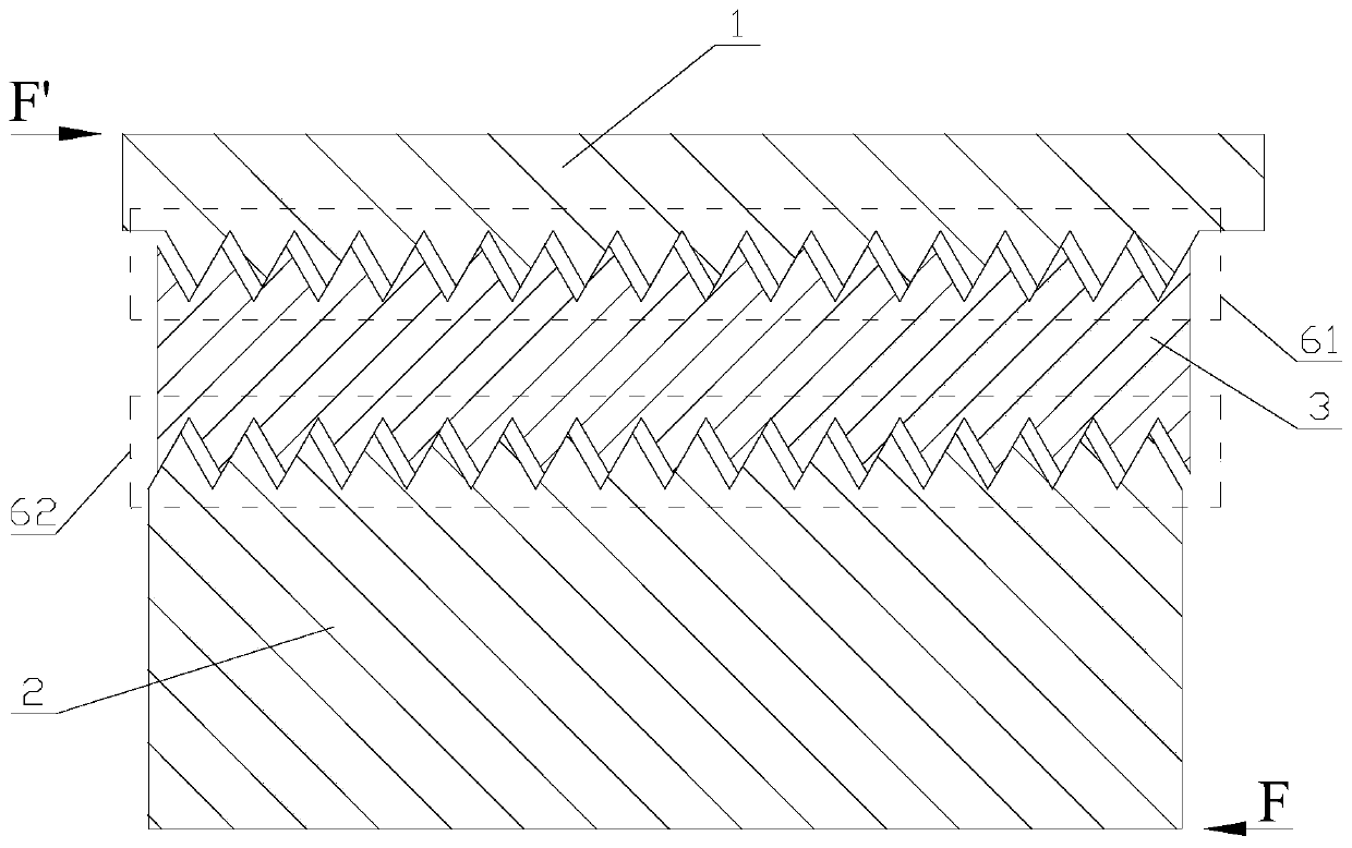
[0038] Part or all of the threads on the inner surface of the nut 1 or in the meshing area on the outer surface of the screw are correction threads 10. The correction thread 10 refers to a thread whose pitch and pitch have been corrected. The correction thread The correction value of the thread pitch of the thread 10 is positively related to the load borne by the correction thread 10 ...

Embodiment 2

[0045] Such as figure 1 , Figure 6 and Figure 7As shown, a load uniform distribution method for the planetary roller screw in Embodiment 1 provided in this embodiment, there are two meshing regions 6 on the planetary ball screw, and the load uniform distribution method is implemented as follows:

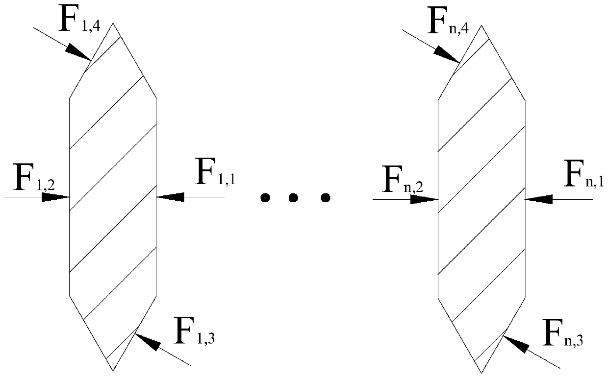
[0046] The pitches of some or all of the threads in the meshing region 6 are corrected according to the load borne by each thread in the meshing region 6 to obtain the corrected thread 10 .

[0047] Usually, only the thread pitch of some of the threads at both ends of the meshing area 6 is corrected, because according to the results of finite element analysis or actual calculation, it can be seen that the loads on the threads at both ends of the meshing area 6 are much greater than those at the middle of the meshing area 6. The load on the thread.

[0048] After the thread pitch is corrected, when the nut 1 and the screw 2 mesh, the thread teeth in the middle of the meshing are...


PUM


Abstract

The invention discloses a planetary roller screw and belongs to the field of roller screw production. The planetary roller screw comprises a nut, a screw rod and a plurality of rollers. The screw rod is co-axially arranged in the nut. A part or all of screw teeth in each of mesh regions on the inner surface of the nut and the outer surface of the screw rod are corrected screw teeth. Correction values of screw spaces of the corrected screw teeth are in positive correlation with load applied to the corrected screw teeth. The invention further discloses a load uniformly distributing method. According to the load applied to the each screw teeth in the mesh regions, the screw spaces of part or all of the screw teeth in the mesh region are corrected to form the corrected screw teeth. The planetary roller screw, with volume thereof maintained, is better in bearing capacity and applicable to environments with high requirements to the roller screw.

Description

technical field [0001] The invention relates to the field of roller screw manufacturing, in particular to a planetary roller screw and a method for uniform load distribution for the planetary roller screw. Background technique [0002] The planetary roller screw is a mechanism that converts rotary motion into linear motion. It is often used in CNC machining, aerospace electromechanical and other fields, such as electromechanical actuators. [0003] Due to the increasingly stringent requirements for the space occupied by electromechanical actuators and the output force, this requires that the roller screw as a key transmission component not only has a smaller lead, but also has a higher load-bearing capacity than ordinary load-bearing indicators, so If the ordinary roller screw is used as the transmission part of the electromechanical actuator, the end of the meshing screw teeth will easily fall off, which will lead to the failure of the transmission of the roller screw. [...

Claims


Application Information

Patent Timeline
Patent Type & Authority Patents(China)
IPC IPC(8): F16H25/22
Inventor 徐强赵国平王水铭黄玉平崔佩娟
Owner BEIJING RES INST OF PRECISE MECHATRONICS CONTROLS
Features
  • R&D
  • Intellectual Property
  • Life Sciences
  • Materials
  • Tech Scout
  • Unparalleled Data Quality
  • Higher Quality Content
  • 60% Fewer Hallucinations
Learn More