Direct-acting electromagnetic valve

A solenoid valve, direct-acting technology, applied in the field of solenoid valves, can solve problems such as low pass rate, performance differences, affecting product pressure resistance and stability, etc., to improve sealing and stability, improve pressure resistance and The effect of airtightness and improving the product qualification rate

Inactive Publication Date: 2015-06-03
SHENZHEN KEYTO FLUID CONTROL
View PDF8 Cites 0 Cited by
  • Summary
  • Abstract
  • Description
  • Claims
  • Application Information

AI Technical Summary

Problems solved by technology

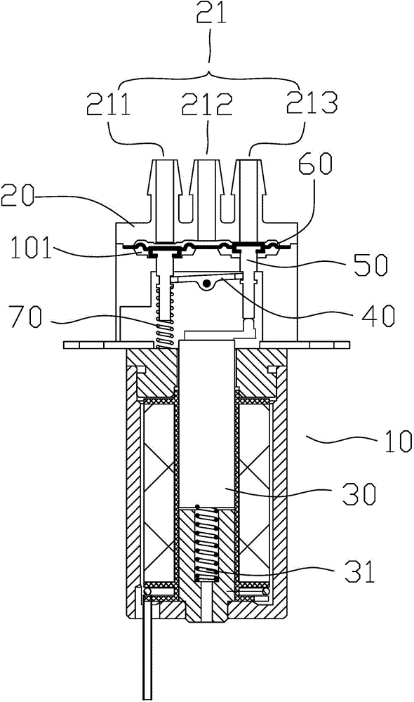
According to its working mode and principle of action, electromagnetic valves are divided into many types. One type of diaphragm valve controls the opening and closing of the valve port through the deformation of the diaphragm. The diaphragm valve in the prior art uses an electromagnet to push the rocker, and then The rocker pushes the diaphragm. In this process, the displacement of the rocker is realized by rotation, so that it is difficult to completely flatten the connection between the diaphragm and the valve port, and the dimensional accuracy of the parts is very high. Only when the spring The elastic force of the diaphragm, the hardness and compression deformation of the diaphragm, the height of the valve port of the bonnet, and the height of the pin shaft hole on the valve body are all just matched. There are errors and performance differences, and it is difficult to achieve a complete match, resulting in unstable product performance and low pass rate; at the same time, the peripheral deformation of the diaphragm is not uniform when rotating, which directly affects the pressure resistance and stability of the product.

Method used


Image

  • Direct-acting electromagnetic valve
  • Direct-acting electromagnetic valve
  • Direct-acting electromagnetic valve

Examples


Embodiment Construction

[0022] The idea, specific structure and technical effects of the present invention will be clearly and completely described below in conjunction with the embodiments and accompanying drawings, so as to fully understand the purpose, scheme and effect of the present invention. It should be noted that, in the case of no conflict, the embodiments in the present application and the features in the embodiments can be combined with each other.

[0023] It should be noted that, unless otherwise specified, when a feature is called "fixed" or "connected" to another feature, it can be directly fixed and connected to another feature, or indirectly fixed and connected to another feature. on a feature. In addition, descriptions such as up, down, left, and right used in the present invention are only relative to the mutual positional relationship of the components of the present invention in the drawings.

[0024] Also, unless defined otherwise, all technical and scientific terms used herei...


PUM


Abstract

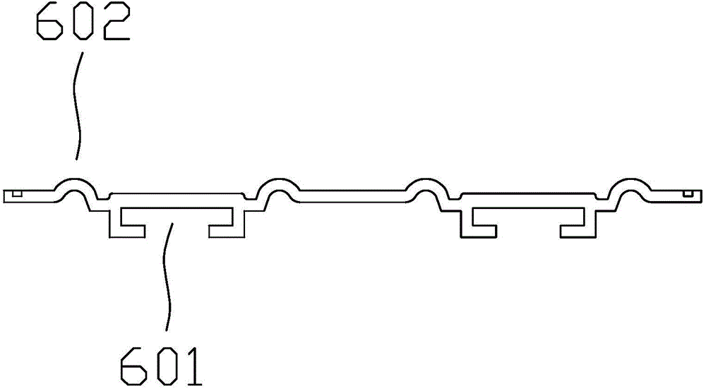
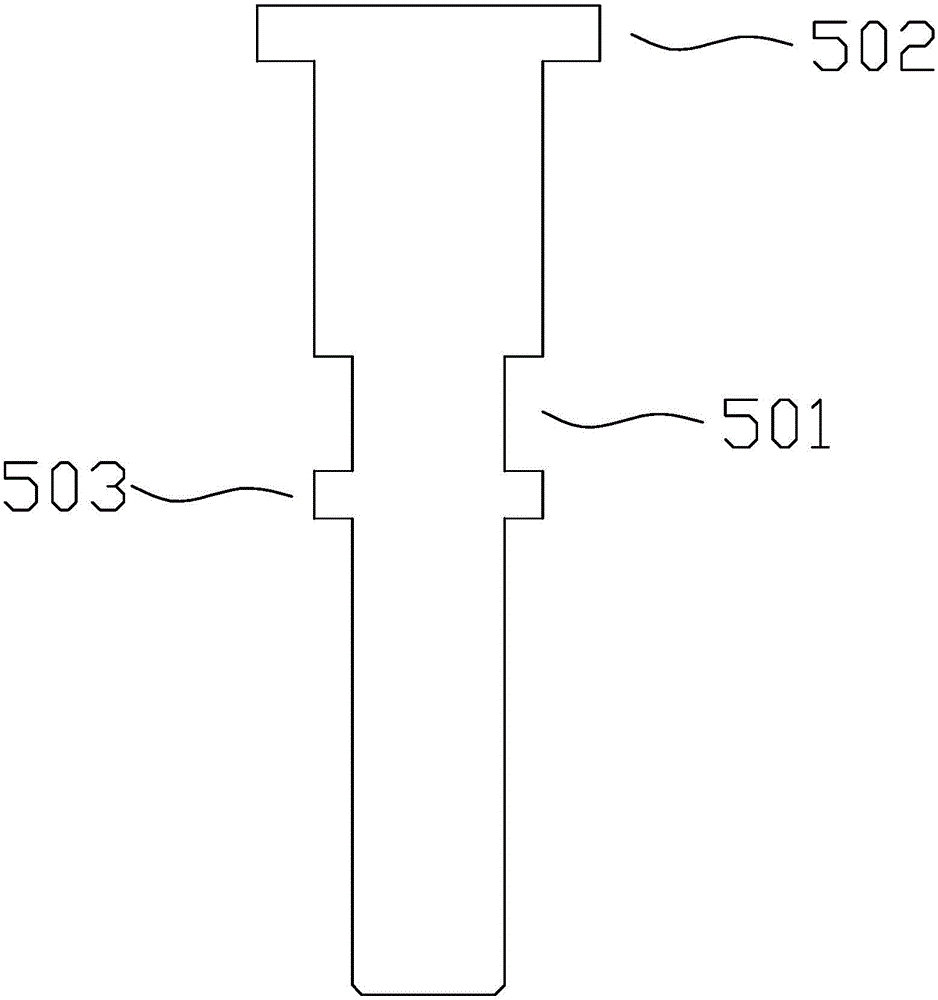
The invention discloses a direct-acting electromagnetic valve, which comprises a valve body, a valve cover, a diaphragm sheet and a movable iron core, wherein the valve body and the valve cover form a cavity, a plurality of openings communicated with the cavity are formed in the valve cover, the diaphragm sheet is arranged in the cavity, the movable iron core can move relative to the valve body, the direct-acting electromagnetic valve comprises a rocker rod, at least one mandril and an elastic element, the rocker rod is rotationally arranged on the valve body for forming a lever structure, and the mandril is connected with the rocker rod, is abutted against the movable iron core, and can be driven by the movable iron core to do linear movement, so that the rocker rod is forced to rotate; the diaphragm sheet is arranged between the openings and the mandril, and is provided with a sealing part at the position corresponding to the openings, the sealing part can seal or open the corresponding opening along with the movement of the mandril; the elastic element is used for resetting the rocker rod. The direct-acting electromagnetic valve has the advantages that the parallel contact of the diaphragm sheet and a valve opening is ensured, the pressure resistance and the sealing performance are improved, the influence of the part precision on the product performance is smaller, and the product qualification rate is improved.

Description

technical field [0001] The invention relates to the field of fluid control, in particular to an electromagnetic valve. Background technique [0002] As a kind of fluid control equipment, solenoid valve is widely used in various fields of modern industry. According to its working mode and principle of action, electromagnetic valves are divided into many types. One type of diaphragm valve controls the opening and closing of the valve port through the deformation of the diaphragm. The diaphragm valve in the prior art uses an electromagnet to push the rocker, and then The rocker pushes the diaphragm. In this process, the displacement of the rocker is realized by rotation, so that it is difficult to completely flatten the connection between the diaphragm and the valve port, and the dimensional accuracy of the parts is very high. Only when the spring The elastic force of the diaphragm, the hardness and compression deformation of the diaphragm, the height of the valve port of the ...

Claims


Application Information

Patent Timeline
IPC IPC(8): F16K31/06
CPCF16K11/24F16K31/0624
Inventor 李海波张成肖茜元
Owner SHENZHEN KEYTO FLUID CONTROL
Why Eureka
Try Eureka