Evaporated fuel treatment device for internal combustion engine

a technology of evaporation fuel treatment and internal combustion engine, which is applied in the direction of machines/engines, mechanical equipment, instruments, etc., can solve the problem that the diagnostic procedure of closing failure cannot be used in the device, and achieve the effect of efficient detection of closing failur

Inactive Publication Date: 2006-01-24
TOYOTA JIDOSHA KK
View PDF6 Cites 61 Cited by
  • Summary
  • Abstract
  • Description
  • Claims
  • Application Information

AI Technical Summary

Benefits of technology

[0010]Therefore, the invention has an object to provide an evaporated fuel treatment device of an internal combustion engine that can efficiently detect closing failure of a sealing valve (corresponding to the above described charge control valve) for tightly sealing a fuel tank without tank internal pressure being negative in normal control.

Problems solved by technology

However, the diagnosing procedure of the closing failure cannot be used in a device in which the tank internal pressure is not negative in normal control.

Method used


Image

  • Evaporated fuel treatment device for internal combustion engine
  • Evaporated fuel treatment device for internal combustion engine
  • Evaporated fuel treatment device for internal combustion engine

Examples


first embodiment

[Description of Structure of Device]

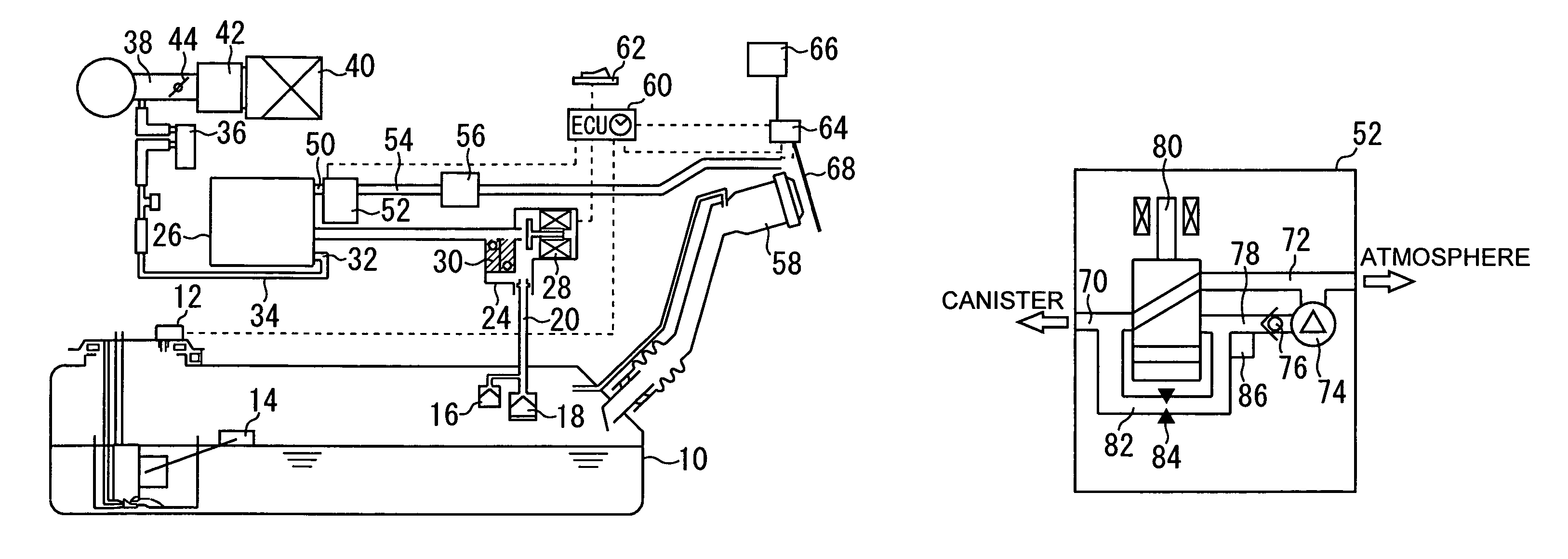
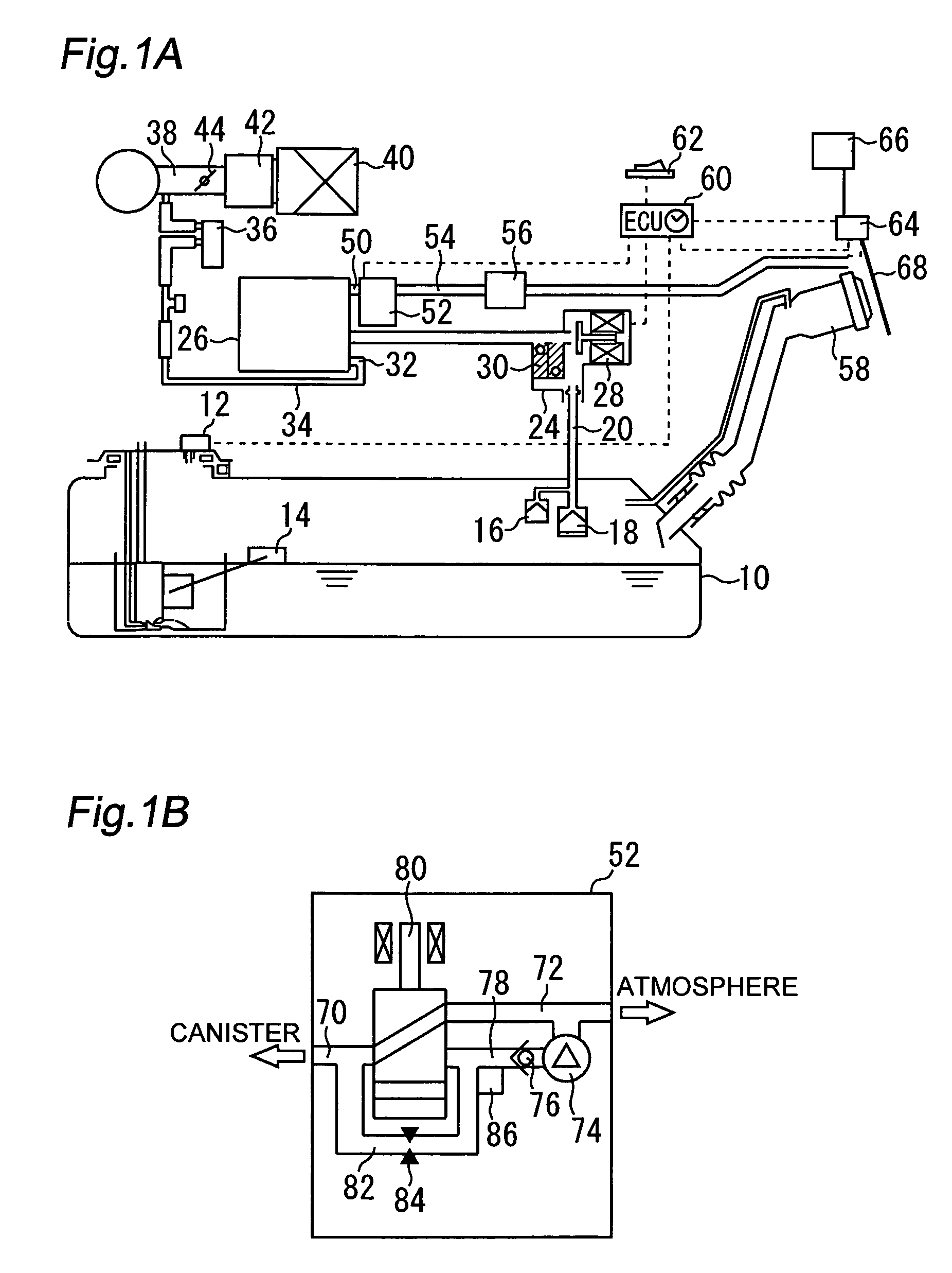
[0034]FIG. 1A illustrates a structure of an evaporated fuel treatment device according to a first embodiment of the invention. As shown in FIG. 1A, the device according to the present embodiment includes a fuel tank 10. The fuel tank 10 has a tank internal pressure sensor 12 for measuring tank internal pressure Ptnk. The tank internal pressure sensor 12 detects the tank internal pressure Ptnk as relative pressure with respect to atmospheric pressure, and generates output in response to a detection value. A liquid level sensor 14 for detecting a liquid level of fuel is placed in the fuel tank 10.

[0035]A vapor passage 20 is connected to the fuel tank 10 via ROVs (Roll Over Valves) 16, 18. The vapor passage 20 has a sealing valve unit 24 on the way thereof, and communicates with a canister 26 at an end thereof. The sealing valve unit 24 has a sealing valve 28 and a pressure control valve 30. The sealing valve 28 is a solenoid valve of a normally clos...

second embodiment

[0090]Next, a second embodiment of the invention will be described with reference to FIGS. 4 and 5. A device according to the present embodiment can be achieved by modifying the device according to the first embodiment such that the ECU 60 performs the closing failure determination of the sealing valve 28 with the below described procedure.

[0091]FIGS. 4A through 4E are timing charts for illustrating abnormality detection performed by the device of the present embodiment for detecting abnormality of the sealing valve 28. More specifically, FIG. 4A shows a state of the sealing valve 28, FIG. 4B shows a state of the switching valve 80, and FIG. 4C shows an operation state of the pump 74. FIG. 4D shows a change in tank internal pressure Ptnk (output of the tank internal pressure sensor 12), and FIG. 4E shows a change in canister side pressure Pcani detected by the pump module pressure sensor 86.

[0092]In the present embodiment, abnormality detection is performed during the parking of the...

third embodiment

[0126]Next, a third embodiment of the invention will be described with reference to FIG. 6. An evaporated fuel treatment device according to the present embodiment can be achieved by modifying the device according to the second embodiment such that the ECU 60 performs a routine shown in FIG. 6 instead of the routine shown in FIG. 5.

[0127]FIG. 6 is a flowchart of a control routine performed by the ECU 60 in the present embodiment for determining whether closing failure occurs in the sealing valve 28. The routine shown in FIG. 6 is the same as the routine shown in FIG. 5, except that Step 152 is omitted, and Steps 170 to 172 are added. In FIG. 6, like reference numerals denote like steps as in FIG. 5, and descriptions thereof will be omitted or simplified.

[0128]In the routine shown in FIG. 6, after negative pressure introduction is started (Steps 140 to 146) and until canister side pressure Pcani reaches below a negative pressure determination value Pth2 (Step 150), procedures of Step...


PUM


Abstract

A sealing valve 28 that controls a communication state between a fuel tank 10 and a canister 26 is provided. During stop of an internal combustion engine, the sealing valve 28 is generally closed, and the canister 26 is opened to the atmosphere. The sealing valve 28 is opened when the internal combustion engine is stopped, and differential pressure exceeding a valve opening determination value is generated between tank internal pressure and atmospheric pressure. A change in the tank internal pressure generated between before and after the sealing valve 28 is opened is detected. When the change in the tank internal pressure is below a predetermined determination value, closing failure of the sealing valve is determined.

Description

BACKGROUND OF THE INVENTION[0001]1. Field of the Invention[0002]The present invention relates to an evaporated fuel treatment device, and more particularly to an evaporated fuel treatment device for treating evaporated fuel generated in a fuel tank without being released into the atmosphere.[0003]2. Background Art[0004]As disclosed in, for example, Japanese Patent Laid-Open No. 2001-193580, an evaporated fuel treatment device is known that includes a canister for adsorbing evaporated fuel generated in a fuel tank. In this device, the fuel tank communicates with the canister via a charge control valve and communicates with an intake passage of an internal combustion engine via a tank pressure control valve.[0005]In the conventional device, the tank pressure control valve is opened to introduce induction negative pressure into the fuel tank, thus keeping tank internal pressure in a negative state, during operation of the internal combustion engine. Keeping the tank internal pressure i...

Claims


Application Information

Patent Timeline
Patent Type & Authority Patents(United States)
IPC IPC(8): G01M19/00G01M99/00F02M25/08
CPCF02M25/089F02M25/0818
Inventor MATSUBARA, TAKUJIKIDOKORO, TORUHYODO, YOSHIHIKO
Owner TOYOTA JIDOSHA KK
Why Eureka
Try Eureka