Device for absorbing floor-landing shock for legged mobile robot

a mobile robot and floor-landing technology, applied in the field of landing shock absorbers, can solve the problems of affecting the size and weight reduction of each leg, the floor reaction force cannot be made to intensively act on the desired position of the foot mechanism, and the lifting motion of the leg cannot be smoothly performed, so as to enhance the damping effect, and achieve the effect of stabilizing the position of the robot more properly

Inactive Publication Date: 2005-04-14
HONDA MOTOR CO LTD
View PDF6 Cites 61 Cited by
  • Summary
  • Abstract
  • Description
  • Claims
  • Application Information

AI Technical Summary

Benefits of technology

[0012] Accordingly, according to the present invention (the first invention), posture stability of the legged mobile robot can be secured easily while reducing the impact load during the landing motion of the leg of the robot.

Problems solved by technology

When this impact load is high, rigidity of each portion of each leg needs to be enhanced in order to resist the load, and furthermore, this will interfere with a size reduction and a weight reduction of each leg.
Therefore, there are times when a lifting motion of the leg cannot be performed smoothly during the movement of the robot, and stumbling is caused.
Additionally, in the landing state of the leg, since the floor reaction force constantly acts on the heel portion of the foot mechanism, the floor reaction force cannot be made to intensively act on a desired position of the foot mechanism (for example, tiptoe or the like) to secure posture stability of the robot.
Therefore, the posture stability of the robot is apt to be impaired by a geometry of a floor, external force or the like.
Furthermore, in the shock absorber, as a result of the use of the hydraulic oil, weight of the shock absorber will be heavy, resulting in interfering with a weight reduction of the robot.
Consequently, the impact load acting on the ground-contacting element may act in a direction that crosses a movable direction thereof depending on a geometry of a floor, so that the impact load may not adequately be reduced, and damage of the shock absorber may be generated.

Method used


Image

  • Device for absorbing floor-landing shock for legged mobile robot
  • Device for absorbing floor-landing shock for legged mobile robot
  • Device for absorbing floor-landing shock for legged mobile robot

Examples


Embodiment Construction

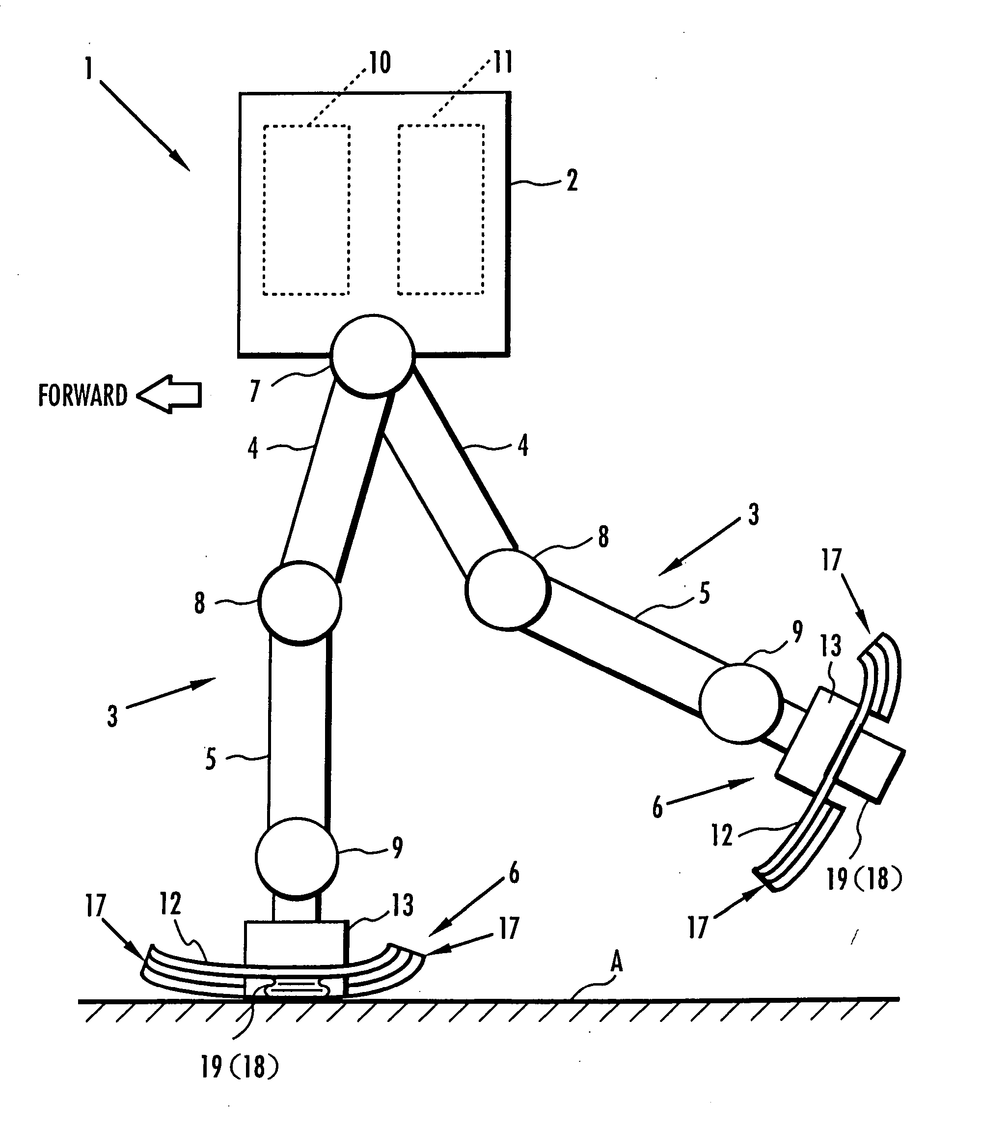
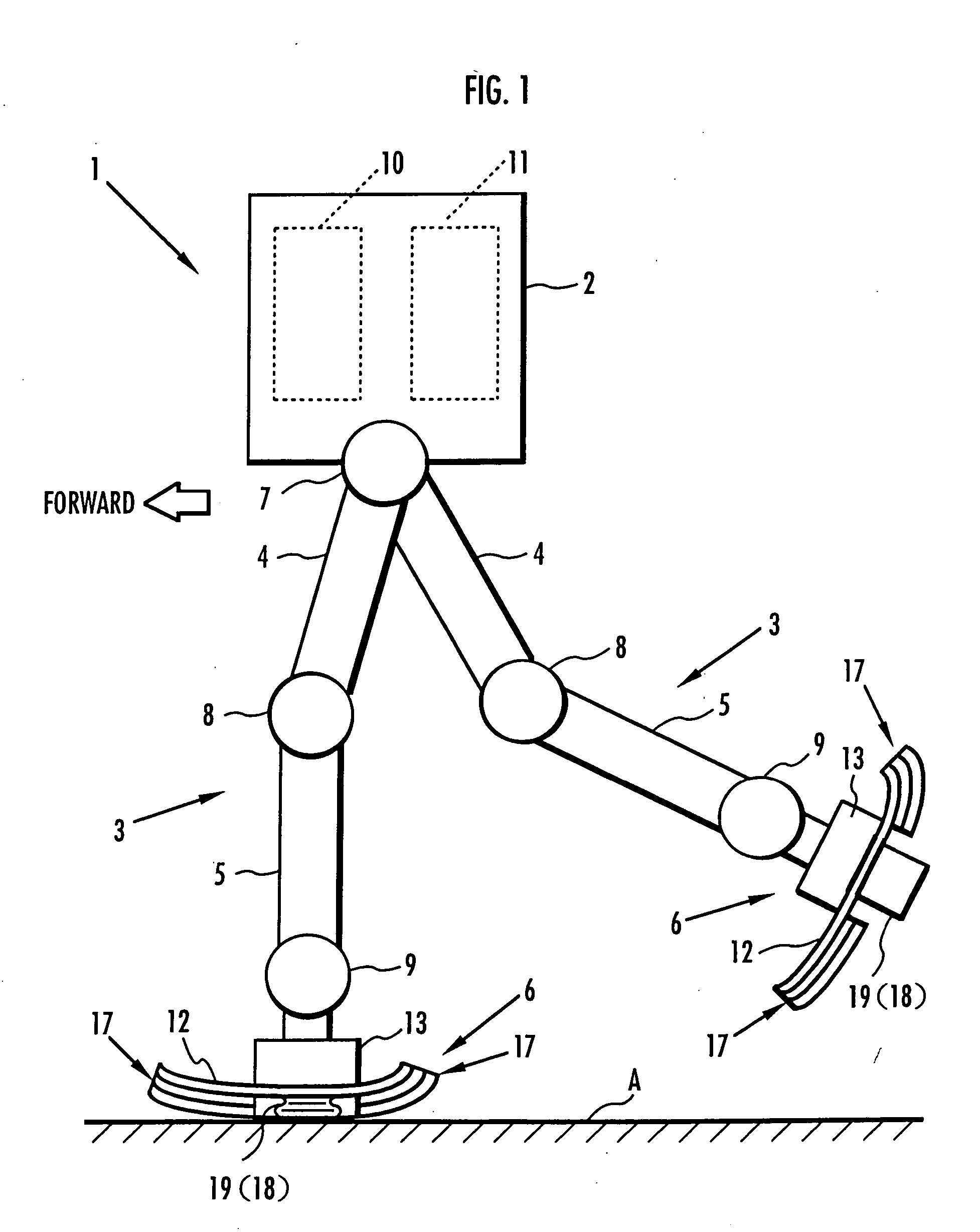
[0045] Referring to FIGS. 1 through 6, a first embodiment of the present invention is described. FIG. 1 is a side view showing an overall basic configuration of a legged mobile robot of the present embodiment in schematic form. As shown in FIG. 1, for example, the legged mobile robot 1 of the present embodiment is a biped mobile robot comprising a pair of (two) legs 3, 3 extendedly disposed from a lower end portion of its upper body 2 (torso). Further, arms and a head may be attached on the upper body 2.

[0046] Each leg 3 is constructed by connecting a thigh 4, a lower leg 5, and a foot mechanism 6 in the order listed through a hip joint 7, a knee joint 8, and an ankle joint 9 from the lower end portion of the upper body 2. More specifically, each leg 3 is adapted to be configured with the thigh 4 extendedly disposed from the lower end portion of the upper body 2 through the hip joint 7, the lower leg 5 connected to a far end portion of the thigh 4 through the knee joint 8, and the ...


PUM


Abstract

A landing shock absorbing device 18 provided in a foot mechanism 6 of a leg of a robot comprises an inflatable and compressible bag-like member 19 (a variable capacity element) on a bottom face side of the foot mechanism 6. The bag-like member 19 is constructed of an elastic material such as rubber. Air in the atmosphere can flow into and out of the bag-like member 19 by inflow / outflow means 20 provided with a solenoid valve 27 and the like. In a landing state of the foot mechanism 6 and in a state immediately after the foot mechanism shifts from the landing state to a lifting state, the solenoid valve 27 is closed to maintain the bag-like member 19 in a compressed state. Furthermore, during the bag-like member 19 in the inflating state during the lifting state of the foot mechanism 6, by controlling timing when the solenoid valve 27 is switched from a valve opening state to a valve closing state, a height of the bag-like member 19 in a compression direction is controlled to be a height suitable for a gait type of the robot. Thereby, posture stability of the robot can be secured easily while reducing a impact load in the landing motion of the leg of the legged mobile robot, and further, a lightweight configuration can be achieved.

Description

TECHNICAL FIELD [0001] The present invention relates to a landing shock absorber for reducing an impact load during a landing motion of a leg of a legged mobile robot. BACKGROUND ART [0002] In a legged mobile robot such as a biped mobile robot equipped with a plurality of legs, each leg is brought into contact with a floor through a ground-contacting face portion of a foot mechanism provided on a far end portion thereof. More particularly, the foot mechanism is a mechanism connected to a joint on the farthest end side of each leg (an ankle joint). The legged mobile robot moves by lifting and landing motions of each leg. More particularly, the lifting and landing motions are a repetition of motions that while at least one leg of a plurality of legs as a supporting leg maintains a foot mechanism of the supporting leg in a ground-contacting state, the other leg as a free leg lifts a foot mechanism of the free leg from its ground-contacting location into the air and moves the same, and ...

Claims


Application Information

Patent Timeline
Patent Type & Authority Applications(United States)
IPC IPC(8): B25J19/00B25J5/00B62D57/032F16F9/04
CPCB25J19/0091F16F9/0481B62D57/032B25J5/00
Inventor TAKENAKA, TORUGOMI, HIROSHIHAMAYA, KAZUSHITAKEMURA, YOSHINARIMATSUMOTO, TAKASHIYOSHIIKE, TAKAHIDENISHIMURA, YOICHIAKIMOTO, KAZUSHIYOKOYAMA, TARO
Owner HONDA MOTOR CO LTD
Why Eureka
Try Eureka