
Power cable spacing clamp

A technology of power cables and spacers, which is applied in the direction of pipe supports, pipes/pipe joints/fittings, mechanical equipment, etc., can solve problems that affect the safe and stable operation of power cables, affect the current carrying capacity of power cables, and cannot perform power outage rectification, etc., to achieve Easy to install and implement, simple to operate, and improve the effect of isolation

Inactive Publication Date: 2015-06-03
STATE GRID CORP OF CHINA +2
View PDF7 Cites 3 Cited by
  • Summary
  • Abstract
  • Description
  • Claims
  • Application Information

AI Technical Summary

Problems solved by technology

[0002] As we all know, cable tunnels, cable trenches, cable interlayers, cable shafts, etc. are very densely populated areas of power cables, and the cables are superimposed and squeezed together. Since the current carrying capacity of the power cables has a great influence on the ambient temperature of the cables, the cables operate at high It will generate heat under the condition of high load current operation, so the temperature will be higher when superimposed and squeezed together, which not only greatly affects the current carrying capacity of the power cable, but also has the hidden danger of cable fire, which seriously affects the power supply. The cables run safely and stably; in addition, for some cables that have been corroded and peeled off for a long time, the power failure rectification cannot be carried out due to their overlapping and overlapping.

Method used


Image

  • Power cable spacing clamp
  • Power cable spacing clamp
  • Power cable spacing clamp

Examples


Embodiment Construction

[0013] The present invention will be further described below in conjunction with accompanying drawing:

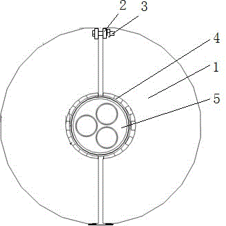
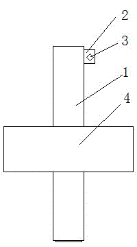
[0014] As shown in the figure, a power cable interval clamp is characterized in that two pieces of insulating material are combined to form an annular spacer 1, the inner wall of the annular spacer 1 is provided with anti-slip teeth, and one end of the two spacers 1 The outer wall is connected by a soft sheet, and the other end is provided with a corresponding connecting lug 2. The connecting lug 2 is provided with a connecting hole, and the bolt 3 passes through the connecting hole to connect with the nut. The two spacers 1 The inner wall of the inner wall is respectively provided with a semicircular sleeve 4, the inner end surface of the sleeve 4 is provided with anti-slip teeth, the spacer 1 and the sleeve 4 are in a cross vertical shape, and the spacer 1 is arranged in the middle of the sleeve 4 to To improve the isolation effect of the power cable 5, one end of the two...


PUM


Abstract

The invention provides a high-voltage power cable spacing technology, particularly a power cable spacing clamp. The power cable spacing clamp is characterized in that two spacing pieces are arranged and combined to form an annular spacing piece; antiskid teeth are arranged on the inner wall of the annular spacing piece; the outer wall at one end of each of the two spacing pieces is connected by soft sheets, and the other end is provided with corresponding connection lugs; connecting holes are formed in the connection lugs; and a bolt is connected with a screw cap after penetrating through the connecting holes. The sleeve and the spacing pieces are made of light plastics with sound insulation, so the clamp is sleeved to the power cable when in use; then, the bolt penetrates through the connecting holes in the two connection lugs; and the sleeve or the spacing pieces are fixed by a nut. To fit the power cables with different section sizes, the inner diameter of the cable clamp or the sleeve can be made into a variety of sizes and specifications. And therefore, the power cable spacing clamp has the advantages of simple operation, convenience in installation and operation, safe and reliable power transmission and the like, and is particularly applied to use in areas with thoroughly dense power cables such as cable tunnels, cable channels, cable interlayers and cable shafts, etc.

Description

technical field [0001] The invention relates to the technical field of electric power, in particular to a power cable interval clip used in places where power cables are densely packed, such as cable tunnels, cable trenches, and cable shafts. Background technique [0002] As we all know, cable tunnels, cable trenches, cable interlayers, cable shafts, etc. are very densely populated areas of power cables, and the cables are superimposed and squeezed together. Since the current carrying capacity of the power cables has a great influence on the ambient temperature of the cables, the cables operate at high It will generate heat under the condition of high load current operation, so the temperature will be higher when superimposed and squeezed together, which not only greatly affects the current carrying capacity of the power cable, but also has the hidden danger of cable fire, which seriously affects the power supply. The cables run safely and stably; in addition, some cables t...

Claims


Application Information

Patent Timeline
Patent Type & Authority Applications(China)
IPC IPC(8): F16L3/10
CPCF16L3/1075
Inventor 姚晓林邢闽苏彦洁李健张卫东毕国威张洁
Owner STATE GRID CORP OF CHINA
Learn More