Gas filling apparatus and gas filling method

A filling device and filling method technology, applied in container filling methods, gas/liquid distribution and storage, gas processing applications, etc., can solve problems such as gas pressure rise and gas flow rate are too large

Inactive Publication Date: 2015-06-03
KOBE STEEL LTD
View PDF9 Cites 10 Cited by
  • Summary
  • Abstract
  • Description
  • Claims
  • Application Information

AI Technical Summary

Problems solved by technology

Therefore, due to the above-mentioned pressure difference, the gas flow rate may become too large, and the pressure of the gas supplied to the gas tank may rise sharply.

Method used


Image

  • Gas filling apparatus and gas filling method
  • Gas filling apparatus and gas filling method
  • Gas filling apparatus and gas filling method

Examples


Embodiment Construction

[0031] Embodiments for implementing the present invention will be described in detail below with reference to the drawings.

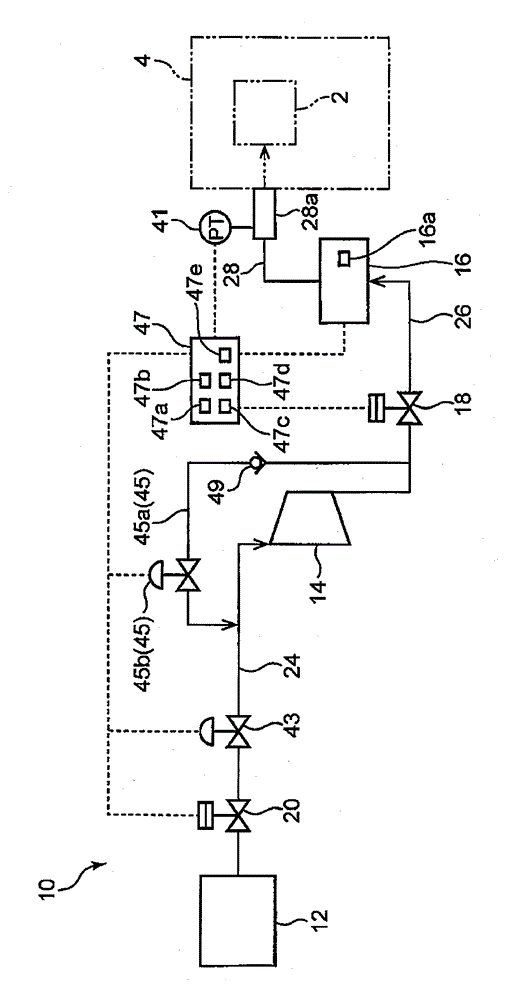
[0032] The gas filling device 10 of the present embodiment is a device for supplying hydrogen gas to the fuel cell vehicle 4, and is installed, for example, in a hydrogen station as a hydrogen gas supply station. The fuel cell vehicle 4 is an example of a tank-mounted device on which the gas tank 2 is mounted. .

[0033] The gas filling device 10 includes a pressure accumulator 12 for storing hydrogen, a compressor 14 for sucking the hydrogen in the pressure accumulator 12 and discharging the sucked hydrogen, and sending the hydrogen discharged from the compressor 14 to the gas tank 2. Distributor 16, a first on-off valve 18 as an on-off valve on the discharge side, and a second on-off valve 20 as an on-off valve on the suction side.

[0034] Hydrogen gas is stored at a predetermined pressure (for example, 40 MPa) in the accumulator 12 . One end of a ...


PUM


Abstract

A gas filling apparatus in the present invention includes an accumulator, a compressor, a pressure sensor for detecting the pressure of gas delivered from a dispenser to be delivered to a gas tank, a regulating valve for regulating the gas flow rate, and a controller. To prevent a rapid rise in pressure of gas supplied to the gas tank, the controller includes an opening control unit for controlling the opening of the regulating valve when a detected value of the pressure sensor is lower than a pressure corresponding to the gas pressure in the accumulator by a predetermined value or more, and a compression control unit for controlling drive of the compressor so that the compressor compresses sucked gas when a pressure difference of a pressure detected by the pressure sensor from a pressure corresponding to the gas pressure in the accumulator becomes a value smaller than the predetermined value.

Description

technical field [0001] The present invention relates to a gas filling device and a gas filling method. Background technique [0002] Conventionally, as disclosed in JP 2012-77858 A, there is known a gas filling device that supplies gas to a gas tank mounted on a tank mounting device. This gas filling device is provided with a pressure accumulator for storing gas, a compressor for sucking and compressing the gas stored in the pressure accumulator, and a gas tank for sending the gas discharged from the compressor to the gas tank of the tank-mounted device. Send out the nozzle. [0003] Japanese Patent Application Laid-Open No. 2005-155486 discloses a reciprocating compressor for compressing gas and supplying it to a supply destination. A suction line and a discharge line are connected to the cylinder of the compressor. By reciprocating the piston, the gas sucked into the cylinder from the suction line can be compressed and discharged from the discharge line. On the other h...

Claims


Application Information

Patent Timeline
Patent Type & Authority Applications(China)
IPC IPC(8): F17C5/06F17C13/02F17C13/04
CPCF17C5/06F17C2205/0326F17C2221/012F17C2223/0123F17C2223/036F17C2225/0123F17C2225/036F17C2250/043F17C2250/0689F17C2265/065F17C5/007F17C2223/035F17C2227/0164F17C2227/0337F17C2250/0636F17C2250/072F17C2260/023F17C2270/0139F17C2250/03Y02E60/32F17C13/00F17C13/04F04B49/03
Inventor 高野雅士名仓见治姥拓郎
Owner KOBE STEEL LTD
Why Eureka
Try Eureka