
Heat pump system for vehicle

A heat pump system, electric vehicle technology, applied in heat pumps, vehicle components, lighting and heating equipment, etc., can solve the problems of heat pump system performance degradation, increased power consumption, reduced driving distance, etc., to improve space availability and driving distance improvement. , the effect of reducing the loss of internal pressure

Inactive Publication Date: 2015-06-03
HYUNDAI MOTOR CO LTD +1
View PDF0 Cites 4 Cited by
  • Summary
  • Abstract
  • Description
  • Claims
  • Application Information

AI Technical Summary

Problems solved by technology

[0011] However, when the heat pump system of the related art described above requires dehumidification while operating in the heating mode in winter, it must stop operating in the heating mode, change to the heating mode using the PTC heater, and then change to the cooling mode, so that due to the Noise and reduced durability due to frequent changes between cooling and cooling modes, and overall performance of the heat pump system
[0012] In addition, when the dehumidification mode is frequently operated, the power consumption increases due to the expansion of the use range of the PTC heater, so the overall driving distance with the same power is reduced

Method used


Image

  • Heat pump system for vehicle
  • Heat pump system for vehicle
  • Heat pump system for vehicle

Examples


Embodiment Construction

[0037] Reference will now be made in detail to various embodiments of the invention, examples of which are illustrated in the accompanying drawings and in the description below. While the invention has been described in conjunction with exemplary embodiments, it will be understood that present description is not intended to limit the invention to those exemplary embodiments. On the contrary, the invention is intended to cover not only the exemplary embodiments, but also various alternatives, modifications, equivalents and other embodiments, which may be included within the spirit and scope of the invention as defined by the appended claims .

[0038] Exemplary embodiments of the present invention will be described in detail below with reference to the accompanying drawings.

[0039] First of all, the exemplary embodiments described herein and the configurations shown in the drawings are the most preferred exemplary embodiments of the present invention, but do not completely c...


PUM


Abstract

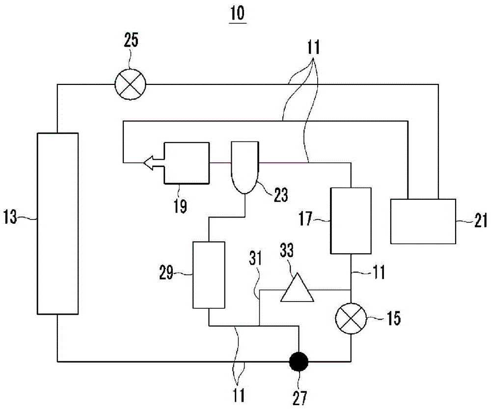
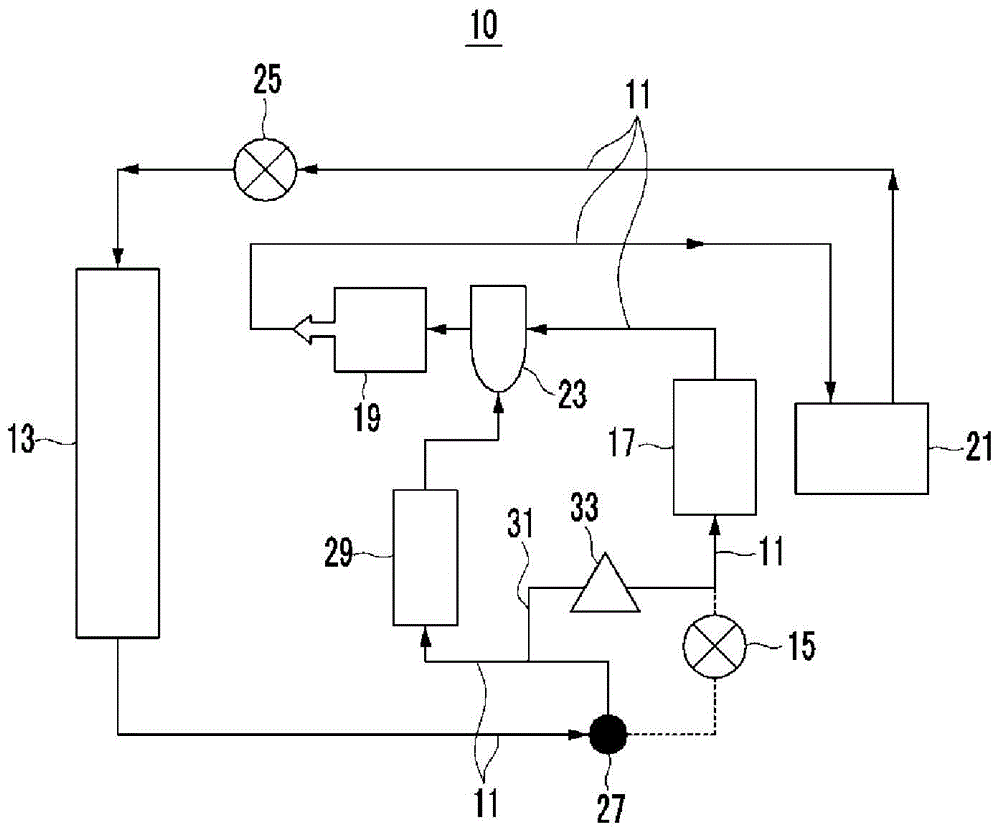
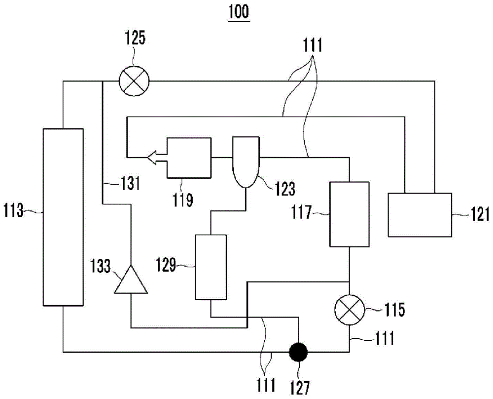
A heat pump system for a vehicle may include an outdoor condenser, an expansion valve, an evaporator, a compressor, and an indoor condenser that primarily condenses the refrigerant compressed through the compressor and is connected with the outdoor condenser, in which the outdoor condenser, the expansion valve, the evaporator, the compressor, and the indoor condenser are connected through refrigerant pipes, a first valve disposed in the refrigerant pipe between the outdoor condenser and the expansion valve; a chiller connected with the first valve through the refrigerant pipe, between the evaporator and the compressor, and controls the temperature of the refrigerant by exchanging heat; a connection pipe selectively allowing some of the refrigerant flowing into the chiller in a dehumidifying mode; and a second valve disposed in the connection pipe.

Description

[0001] Cross References to Related Applications [0002] This application claims priority from Korean Patent Application No. 10-2013-0148737 filed on December 2, 2013, the entire contents of which are hereby incorporated by reference for all purposes. technical field [0003] The invention relates to a heat pump system for a vehicle. More specifically, the present invention relates to a heat pump system for a vehicle, which increases the driving distance of the vehicle by reducing the use of the PTC heater, and which can utilize the The heating mode runs continuously in the dehumidification mode, improving its overall efficiency. Background technique [0004] Generally, an automatic air conditioning system includes an air conditioning module for heating / cooling the interior of the vehicle. [0005] Such an air conditioning module is designed to cool the interior of the vehicle using a heat exchange medium that is discharged from the compressor and exchanges heat through th...

Claims


Application Information

Patent Timeline
Patent Type & Authority Applications(China)
IPC IPC(8): F25B29/00F25B13/00F25B41/04B60H1/00
CPCB60H1/00899F25B41/20F25B6/04B60H1/00914B60H2001/00949F25B30/02F25B41/385F25B41/39
Inventor 李吉雨
Owner HYUNDAI MOTOR CO LTD
Learn More