Heat exchanger fin, heat exchanger and manufacturing method of heat exchanger fin

A heat exchanger and fin technology, applied in the field of heat exchangers, can solve the problems of complex process, high processing cost, and unfavorable condensate discharge of external fluid, and achieve the effects of increasing disturbance, smooth flow and improving heat exchange performance.

Inactive Publication Date: 2015-06-03
SANHUA HANGZHOU MICRO CHANNEL HEAT EXCHANGER
View PDF2 Cites 6 Cited by
  • Summary
  • Abstract
  • Description
  • Claims
  • Application Information

AI Technical Summary

Problems solved by technology

[0004] The heat dissipation fins in the prior art are usually made of aluminum foil, and the louver structure is set on the two side walls of the fin to increase the heat exchange area and improve the heat exchange efficiency, but the louver structure is easy to cause dust accumulation of the external fluid and is not conducive to condensed water At the same time, the heat dissipation fin is formed by multiple processing processes, the main process is formed by precision equipment and hob rolling, the process is complicated and the processing cost is high

Method used


Image

  • Heat exchanger fin, heat exchanger and manufacturing method of heat exchanger fin
  • Heat exchanger fin, heat exchanger and manufacturing method of heat exchanger fin
  • Heat exchanger fin, heat exchanger and manufacturing method of heat exchanger fin

Examples


Embodiment Construction

[0031] The present invention will be further described below in conjunction with the drawings and specific embodiments:

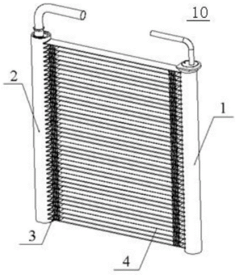
[0032] The present invention discloses a heat exchanger. In this embodiment, a parallel flow heat exchanger is taken as an example for description, see figure 1 , The heat exchanger 10 includes a first header 1 and a second header 2 for collecting and distributing internal fluids, connecting the first header 1 and the second header 2 and located between the two Flat tubes 4 and fins 3 arranged between adjacent flat tubes 4.

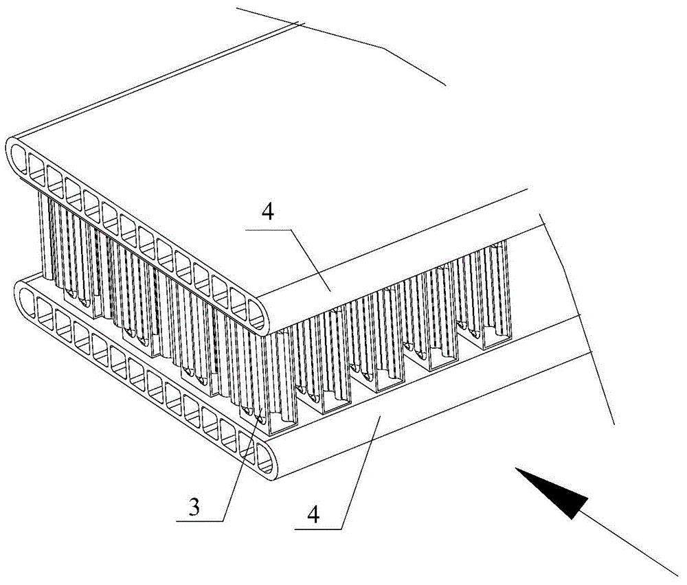
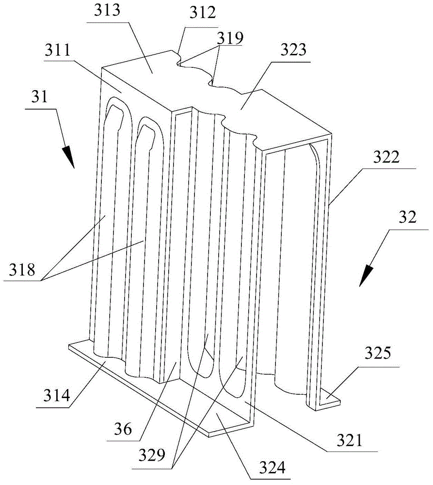
[0033] figure 2 It is a schematic diagram of the structure of adjacent flat tubes 4 and fins 3, where the arrow direction is the flow direction of the external fluid is also the length direction of the fins, the cross section of the fins 3 in the direction of the external fluid flow is rectangular or trapezoidal; adjacent flat tubes There are fins 3 arranged therebetween, and the fins 3 include a plurality of fin units arranged as shown in...


PUM


Abstract

The invention provides a heat exchanger fin. The heat exchanger fin comprises a plurality of fin units which are integrally connected in a certain manner; the sections of the fin units in the circulation direction of an outside fluid are approximately rectangular or trapezoidal; in the length direction of the fin, the adjacent fin units are connected by use of corresponding tops and corresponding first roots and second roots; in addition, the adjacent fin units are arranged in a ladder pattern, and gaps are formed between corresponding first sidewalls and corresponding second sidewalls; in the width direction of the fin, the adjacent fins are connected by use of the corresponding first roots and the corresponding second roots; an reinforcing element serving as a lug and/or a concave portion is integrally formed on one of the first sidewall and the second sidewall, so that the bearing strength of the fin units can be enhanced and the surface heat exchange area of the fin also can be increased; meanwhile, the reinforcing element is matched with the gaps to increase the turbulence between the fin and the fluid, and consequently, the heat exchange efficiency of the heat exchanger with the fin can be improved.

Description

Technical field [0001] The invention relates to a heat exchanger, in particular to a heat exchanger with fins. Background technique [0002] In recent decades, the air-conditioning industry and refrigeration industry have developed rapidly. As one of the main components of air-conditioning and refrigeration equipment, heat exchangers also need to be improved and optimized in accordance with market requirements; existing parallel flow heat exchangers It has the characteristics of high refrigeration efficiency, small size, light weight and strong pressure resistance, which can well meet the requirements of the market. [0003] Parallel flow heat exchangers include porous flat tubes, radiating fins and collecting tubes. Collecting tubes are arranged at both ends of the porous flat tubes, and cooling fins with shutters are arranged between adjacent porous flat tubes; The collecting pipe is used for distributing and collecting refrigerant; the heat dissipation fins are used for strengt...

Claims


Application Information

Patent Timeline
Patent Type & Authority Applications(China)
IPC IPC(8): F28F1/12F25B39/00B23P15/26
Inventor 不公告发明人
Owner SANHUA HANGZHOU MICRO CHANNEL HEAT EXCHANGER
Why Eureka
Try Eureka