
Intensity testing device for lamp light source

A technology of strength testing and light source, which is applied in the direction of applying stable tension/pressure to test the strength of materials, which can solve the problems of testing fluorescent lamps, personal injury, and the inability to guarantee the reliability of fluorescent lamps, and achieve the effect of ensuring strength and reliability.

Inactive Publication Date: 2015-06-03
OCEANKING DONGGUAN LIGHTING TECH +2
View PDF0 Cites 0 Cited by
  • Summary
  • Abstract
  • Description
  • Claims
  • Application Information

AI Technical Summary

Problems solved by technology

Fluorescent lamps are the latest type of energy-saving light source. They have the advantages of long life, high luminous efficiency, and good color rendering. Among them, the structure of fluorescent lamps is more fragile than other light sources and is easy to break. When installing fluorescent lamps, it is generally necessary to use In order to hold the lamp tube and screw it into the lamp holder, the lamp tube will be pressed hard when screwing in the lamp holder. Once the lamp tube is under too much force, it may cause the lamp tube to break and cause personal injury. Therefore, the intensity of the fluorescent lamp needs to be determined. Guarantee, but there is no special device for testing the intensity of fluorescent lamps in the prior art, and the reliability of fluorescent lamps in actual use cannot be guaranteed

Method used


Image

  • Intensity testing device for lamp light source
  • Intensity testing device for lamp light source

Examples


Embodiment Construction

[0018] The following will clearly and completely describe the technical solutions in the embodiments of the present invention with reference to the drawings in the embodiments of the present invention.

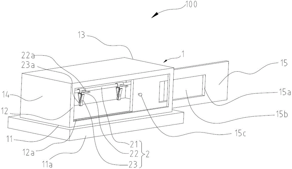
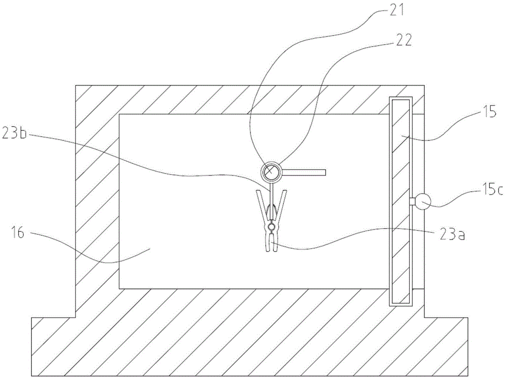
[0019] Please also refer to Figure 1 to Figure 2 , an intensity test device 100 for a lamp light source provided in an embodiment of the present invention includes a box body 1 and a clamping assembly 2, the clamping assembly 2 is arranged in the box body 1, and the clamping assembly 2 is used for The light source (not shown) of the lamp under test is clamped so as to test the intensity of the light source of the lamp under test and ensure the reliability of the light source of the lamp under test in actual use.

[0020] The box body 1 includes an open end (not shown) and a box door 115 . In this embodiment, in order to facilitate the movement of the box body 1, the material of the box body 1 is aluminum alloy. In order to ensure the strength of the box body 1, the wall thi...


PUM

PropertyMeasurementUnit
clamping forceaaaaaaaaaa
thicknessaaaaaaaaaa
thicknessaaaaaaaaaa

Abstract

The invention discloses an intensity testing device for a lamp light source. The intensity testing device comprises a box body and a clamping assembly, wherein the box body comprises an opening end and a box door; the box door is connected to the opening end and forms a sealed space with the opening end; the clamping assembly comprises a hanging rod, at least two connectors and at least two clips; the hanging rod is arranged in the box body, the connectors are slidably connected to the hanging rod, and the clips are arranged on the connectors; each of the clips comprises a clamping part which is made from silicon rubber and is used for clamping a light source of a to-be-tested lamp. According to the intensity testing device for the lamp light source, the intensity of the light source of the to-be-tested lamp is tested by clamping the light source of the to-be-tested lamp in the clamping parts and applying predetermined clamping force to the light source of the to-be-tested lamp by virtue of the clamping parts, and the actual condition that the light source of the to-be-tested lamp is mounted by testing personnel is effectively and truly simulated by using a silicon rubber material which is relatively similar to the fingerprint, so that the intensity and reliability of the light source of the to-be-tested lamp in actual use is effectively ensured.

Description

technical field [0001] The invention relates to the field of lamp lighting, in particular to a device for testing the intensity of a lamp light source. Background technique [0002] Fluorescent lamps, that is, low-pressure mercury lamps, use low-pressure mercury vapor to radiate ultraviolet rays during the discharge process, making phosphors emit visible light. Fluorescent lamps are the latest type of energy-saving light source. They have the advantages of long life, high luminous efficiency, and good color rendering. Among them, the structure of fluorescent lamps is more fragile than other light sources and is easy to break. When installing fluorescent lamps, it is generally necessary to use In order to hold the lamp tube and screw it into the lamp holder, the lamp tube will be pressed hard when screwing in the lamp holder. Once the lamp tube is under too much force, it may cause the lamp tube to break and cause personal injury. Therefore, the intensity of the fluorescent l...

Claims


Application Information

Patent Timeline
Patent Type & Authority Applications(China)
IPC IPC(8): G01N3/08
Inventor 周明杰汪辉
Owner OCEANKING DONGGUAN LIGHTING TECH
Learn More