
Intelligent self-checking method for residual current detection circuit based on signal injection mode

A technology of residual current and detection circuit, which is applied in the direction of measuring devices, measuring electrical variables, instruments, etc., can solve problems such as failure of protection action, line tripping, inconvenience in production and life, etc., to ensure normal power consumption, prevent personal electric shock, The effect of perfect detection method

Inactive Publication Date: 2015-06-03
KAILI POWER SUPPLY BUREAU +1
View PDF7 Cites 8 Cited by
  • Summary
  • Abstract
  • Description
  • Claims
  • Application Information

AI Technical Summary

Problems solved by technology

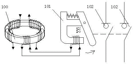
[0004] Therefore, there are great limitations in this solution. Specifically, the disadvantages of traditional leakage protection devices are: 1. The coil of the residual current protector is easily damaged. If the coil detects no residual current, it will be judged that the line has no leakage; The current of the current is also zero. At this time, the leakage protection device is useless, and the proper protection action cannot be achieved. It is difficult to judge whether the coil is damaged, and it needs to be checked manually at fixed points.
2. To check whether the residual current protector works normally, add a control button to the leakage protection device, artificially cut off the circuit, and cause the magnetic field on the coil to change to detect whether there is residual current in the line, but press the button The detection will cause the line to trip, which will bring great inconvenience to people's normal production and life, so this detection method is rigid and inapplicable

Method used


Image

  • Intelligent self-checking method for residual current detection circuit based on signal injection mode
  • Intelligent self-checking method for residual current detection circuit based on signal injection mode
  • Intelligent self-checking method for residual current detection circuit based on signal injection mode

Examples


Embodiment Construction

[0030] Below in conjunction with the attached in the embodiment of the present invention Figures 2 to 5 , clearly and completely describe the technical solutions in the embodiments of the present invention. Obviously, the described embodiments are only some of the embodiments of the present invention, not all of them. Based on the embodiments of the present invention, all other embodiments obtained by persons of ordinary skill in the art without creative efforts fall within the protection scope of the present invention.

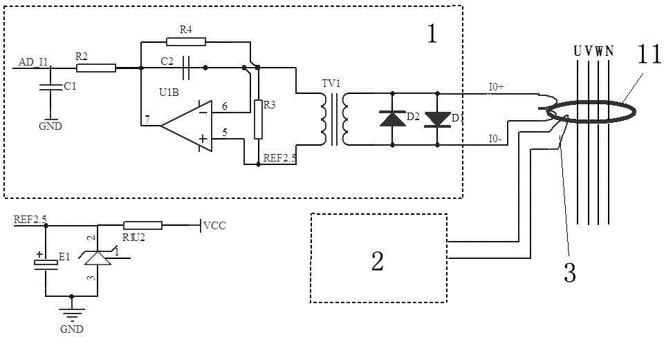
[0031] The present invention includes the current transformer 11 for detecting the remaining circuit 1, and also includes adding a section of winding 3 to the current transformer 1, and the winding 3 is connected with the self-inspection circuit 2 provided with the MCU control module 21.

[0032] The self-inspection circuit 2 injects a self-inspection current into the winding 3 through the MCU control module 21 to the current transformer 11 , and feeds back ...


PUM


Abstract

The invention belongs to the technical field of improvement of the reliability of a residual current protector, and in particular relates to a residual current detection circuit based on a signal injection mode and an intelligent self-checking method for the residual current detection circuit. The intelligent self-checking method comprises the following steps: adding a winding to a current transformer for detecting a residual circuit, and adding a self-checking circuit which is controlled through an MCU control module. The intelligent self-checking method has the advantages that 1 whether a current induction coil is damaged or not is detected; 2 the self-checking is relatively safe and reliable, and tripping operation or blackout is not needed in the self-checking of residual current; 3 the method is relatively safe; and 4 related standards and specifications of information system security levels can be met.

Description

technical field [0001] The invention belongs to the technical field of improving the reliability of a residual current protector, and relates to an intelligent self-inspection method for a signal-injected residual current detection circuit. Background technique [0002] According to the statistics of the fire department, among the fire accidents in the country, electrical fires caused by excess current and residual current accounted for about 1 / 3 of the total; among them, in electrical fire accidents, due to single-phase ground faults of low-voltage lines, the accidents caused by electrical fires accounted for about 1 / 3 of the total. 1 / 2 of fire accidents. It can be seen that the single-phase ground fault of the line is quite serious and common in the current production and life. [0003] The current solution is to install a residual current operated protective device (RCD, hereinafter referred to as a residual current protector) in the low-voltage power grid, which is an e...

Claims


Application Information

Patent Timeline
IPC IPC(8): G01R35/00
Inventor 梁开东严文交周凤灵石祖昌吴志明胡国昌杨昌甫徐建波蒋友权李长海胡晶晶杨道湖
Owner KAILI POWER SUPPLY BUREAU
Learn More