
Alignment mechanism and exposure machine provided with the alignment mechanism

A grating and grating ruler technology, applied in the field of exposure machines, can solve the problems of low exposure accuracy, transmission result error, influence adjustment accuracy, etc., and achieve the effects of high transmission rigidity, high positioning accuracy, and guaranteed stability.

Active Publication Date: 2017-12-22
浙江欧视电科技有限公司
View PDF4 Cites 0 Cited by
  • Summary
  • Abstract
  • Description
  • Claims
  • Application Information

AI Technical Summary

Problems solved by technology

[0003] In the prior art, there have been many alignment mechanisms for adjusting the position error of the PCB board. Although the problems of low exposure accuracy and poor exposure display image due to the failure to adjust the position of the PCB board in the prior art have been solved to a certain extent, due to The adjustment of the PCB board is fine-tuning, and even needs to be accurate to the micron level. The existing alignment mechanism still has the following problems: (1) The position of the PCB board is mainly caused by the error of the angle. The angle adjustment accuracy of the existing alignment mechanism Low, it is generally driven by a traditional rotating motor, which needs to cooperate with the conversion mechanism for transmission. It is difficult to make a breakthrough in the feed speed, acceleration, fast positioning accuracy, etc., and the intermediate conversion mechanism will transmit the result A certain error is caused, and the angle error of the PCB board cannot be accurately adjusted, so that the accuracy cannot be guaranteed; (2) The existing driving mechanism is composed of a motor, a shaft, bearing one, bearing two and a bearing sleeve to drive X, Y and Movement in the direction of rotation. When connecting, one end of the shaft is directly connected to the motor, and there is a gap. The other end of the shaft is supported by a separate deep groove ball bearing. When reversing, there is a gap movement and radial movement first, and the stability is poor. directly affect the accuracy of adjustment

Method used


Image

  • Alignment mechanism and exposure machine provided with the alignment mechanism
  • Alignment mechanism and exposure machine provided with the alignment mechanism
  • Alignment mechanism and exposure machine provided with the alignment mechanism

Examples


Embodiment Construction

[0040] In order to make the purpose, technical solutions and advantages of the embodiments of the present invention more clear, the following will clearly and completely describe the technical solutions of the embodiments of the present invention in conjunction with the drawings of the embodiments of the present invention. Apparently, the described embodiments are some, not all, embodiments of the present invention. Based on the described embodiments of the present invention, all other embodiments obtained by persons of ordinary skill in the art without creative efforts shall fall within the protection scope of the present invention.

[0041] In describing the present invention, it should be understood that the terms "center", "longitudinal", "transverse", "length", "width", "thickness", "upper", "lower", "front", " Orientation or position indicated by "back", "left", "right", "vertical", "horizontal", "top", "bottom", "inner", "outer", "clockwise", "counterclockwise", etc. T...


PUM


Abstract

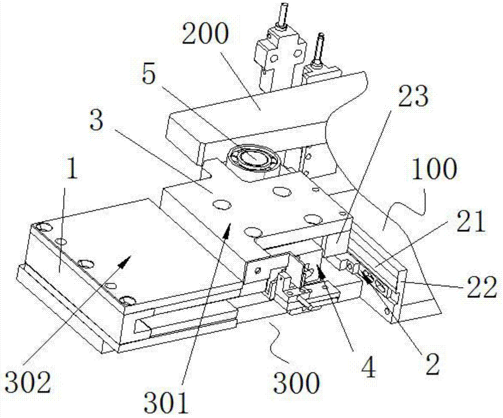
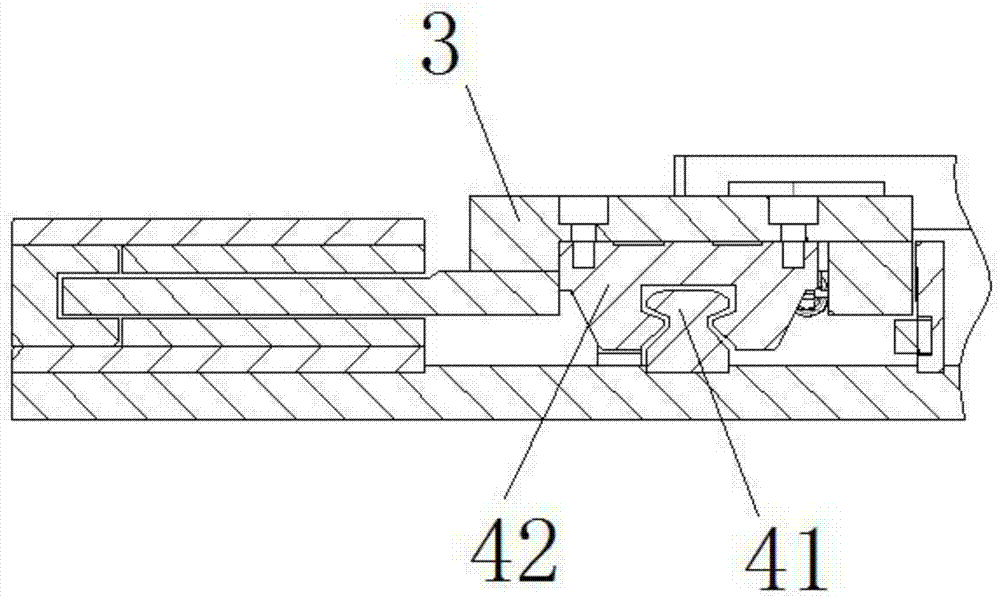
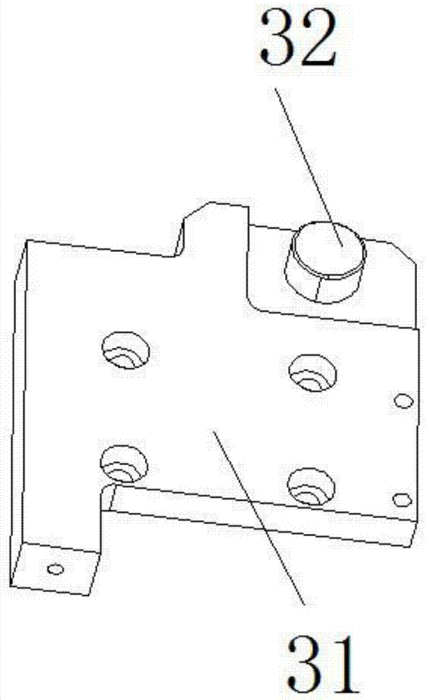
The invention discloses an alignment mechanism, which includes a base assembly, an alignment bracket and an angle adjustment device, the angle adjustment device is arranged on the base assembly, and the angle adjustment device includes a pushing device and is used to drive the The first driving device for the translation of the pushing device, the first driving device includes a linear motor assembly and a grating assembly, the grating assembly includes a grating ruler, a mounting bracket and a grating ruler reading head, and the grating ruler reading head is connected to the pushing device And set parallel to the moving direction of the pushing device, the installation bracket is connected to the base assembly, and the grating ruler is arranged on the installation bracket; an exposure machine is also disclosed, including an exposure machine main body, a light source device, and a control system And an alignment mechanism, the alignment mechanism is installed on the main body of the exposure machine. The exposure machine of the present invention automatically adjusts the installation position through the alignment mechanism, has simple structure, good stability and high adjustment precision.

Description

technical field [0001] The invention relates to the field of exposure technology, in particular to an alignment mechanism capable of automatic alignment and an exposure machine provided with the alignment mechanism. Background technique [0002] When exposing the PCB board by the exposure machine, it is necessary to ensure high exposure accuracy and clearer and more stable graphics. Among them, the positioning of the PCB board is more demanding, so in order to ensure the best position of the PCB board, reduce the position of the PCB board Error, the exposure machine is also specially equipped with an alignment mechanism for adjusting the placement position of the PCB board and reducing the error. [0003] In the prior art, there have been many alignment mechanisms for adjusting the position error of the PCB board. Although the problems of low exposure accuracy and poor exposure display image due to the failure to adjust the position of the PCB board in the prior art have bee...

Claims


Application Information

Patent Timeline
Patent Type & Authority Patents(China)
IPC IPC(8): G03F9/00G03F7/20
Inventor 张方德谢桂平
Owner 浙江欧视电科技有限公司
Learn More