High-tensile copper-clad steel wire rod
A technology of copper-clad steel wire and high tensile strength, applied in the direction of metal/alloy conductors, etc., can solve the problems of poor tensile performance, easy deformation and fracture, etc., to improve tensile performance, improve deformation resistance, and prolong service life Effect
- Summary
- Abstract
- Description
- Claims
- Application Information
AI Technical Summary
Problems solved by technology
Method used
Image
Examples
Embodiment 1
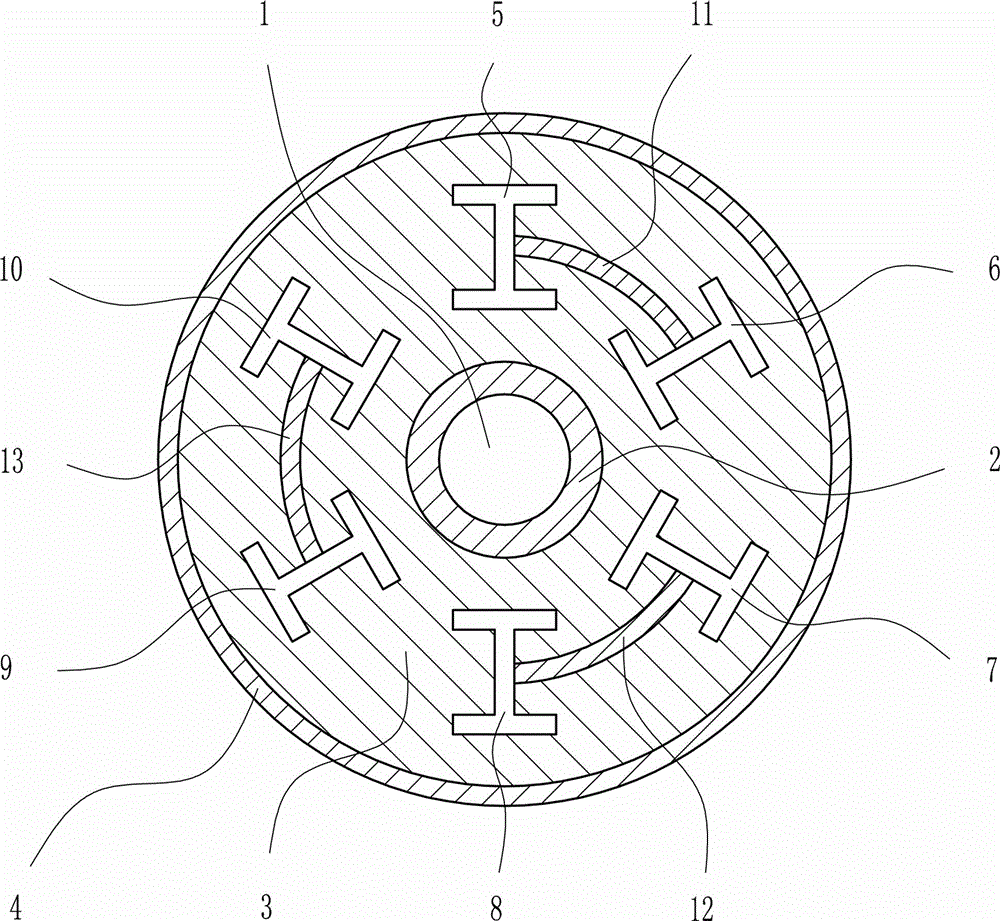
[0032] A high tensile copper clad steel wire, such as figure 1 As shown, including low-carbon steel layer 2, pure iron layer 3, copper-plated layer 4, low-carbon I-beam Ⅰ5, low-carbon I-beam Ⅱ6, low-carbon I-beam Ⅲ7, low-carbon I-beam Ⅳ8, low-carbon I-beam Ⅳ Carbon I-beam Ⅴ9, low-carbon I-beam Ⅵ10.
[0033] The interior of the low-carbon steel layer 2 is provided with a hollow layer 1, and the low-carbon steel layer 2 wraps the hollow layer 1; the exterior of the low-carbon steel layer 2 is provided with a pure iron layer 3, and the interior of the pure iron layer 3 is respectively provided with low-carbon I-beam I5, low-carbon I-beam II6, low-carbon I-beam III7, low-carbon I-beam IV8, low-carbon I-beam V9, and low-carbon I-beam VI10.
[0034] Low-carbon I-steel Ⅰ5, low-carbon I-steel Ⅱ6, low-carbon I-steel Ⅲ7, low-carbon I-steel Ⅳ8, low-carbon I-steel Ⅴ9, low-carbon I-steel Ⅵ10 are uniformly arranged in the pure iron The inside of the layer 3 and the outside of the pure iro...
Embodiment 2
[0038] A high tensile copper clad steel wire, such as figure 1 As shown, including low-carbon steel layer 2, pure iron layer 3, copper-plated layer 4, low-carbon I-beam Ⅰ5, low-carbon I-beam Ⅱ6, low-carbon I-beam Ⅲ7, low-carbon I-beam Ⅳ8, low-carbon I-beam Ⅳ Carbon I-beam Ⅴ9, low-carbon I-beam Ⅵ10.
[0039] The interior of the low-carbon steel layer 2 is provided with a hollow layer 1, and the low-carbon steel layer 2 wraps the hollow layer 1; the exterior of the low-carbon steel layer 2 is provided with a pure iron layer 3, and the interior of the pure iron layer 3 is respectively provided with low-carbon I-beam I5, low-carbon I-beam II6, low-carbon I-beam III7, low-carbon I-beam IV8, low-carbon I-beam V9, and low-carbon I-beam VI10.
[0040] Low-carbon I-steel Ⅰ5, low-carbon I-steel Ⅱ6, low-carbon I-steel Ⅲ7, low-carbon I-steel Ⅳ8, low-carbon I-steel Ⅴ9, low-carbon I-steel Ⅵ10 are uniformly arranged in the pure iron The inside of the layer 3 and the outside of the pure iron ...
Embodiment 3
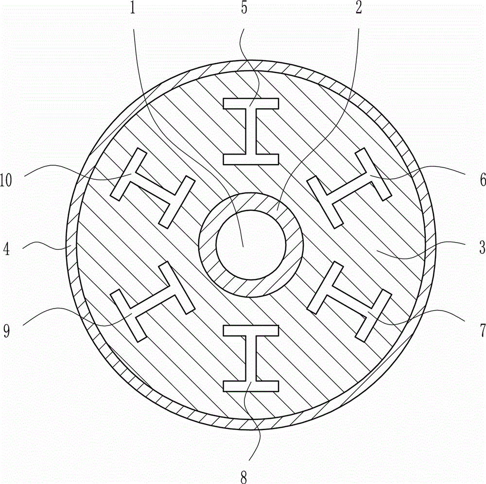
[0049] A high tensile copper clad steel wire, such as Figure 1-2 As shown, including low-carbon steel layer 2, pure iron layer 3, copper-plated layer 4, low-carbon I-beam Ⅰ5, low-carbon I-beam Ⅱ6, low-carbon I-beam Ⅲ7, low-carbon I-beam Ⅳ8, low-carbon I-beam Ⅳ Carbon I-beam Ⅴ9, low-carbon I-beam Ⅵ10.
[0050] The interior of the low-carbon steel layer 2 is provided with a hollow layer 1, and the low-carbon steel layer 2 wraps the hollow layer 1; the exterior of the low-carbon steel layer 2 is provided with a pure iron layer 3, and the interior of the pure iron layer 3 is respectively provided with low-carbon I-beam I5, low-carbon I-beam II6, low-carbon I-beam III7, low-carbon I-beam IV8, low-carbon I-beam V9, and low-carbon I-beam VI10.
[0051] Low-carbon I-steel Ⅰ5, low-carbon I-steel Ⅱ6, low-carbon I-steel Ⅲ7, low-carbon I-steel Ⅳ8, low-carbon I-steel Ⅴ9, low-carbon I-steel Ⅵ10 are uniformly arranged in the pure iron The inside of the layer 3 and the outside of the pure ...
PUM
| Property | Measurement | Unit |
|---|---|---|
| diameter | aaaaa | aaaaa |
| diameter | aaaaa | aaaaa |
| diameter | aaaaa | aaaaa |
Abstract
Description
Claims
Application Information
 - R&D
- Intellectual Property
- Life Sciences
- Materials
- Tech Scout
- Unparalleled Data Quality
- Higher Quality Content
- 60% Fewer Hallucinations
Browse by: Latest US Patents, China's latest patents, Technical Efficacy Thesaurus, Application Domain, Technology Topic, Popular Technical Reports.
© 2025 PatSnap. All rights reserved.Legal|Privacy policy|Modern Slavery Act Transparency Statement|Sitemap|About US| Contact US: help@patsnap.com


