Equipment line cleat of distribution line
A technology for power distribution lines and equipment clips, applied in circuits, electrical components, conductive connections, etc., can solve the problems of prolonged construction time, small contact area between power lines and equipment clips, and reduced line current carrying capacity. Uneven area, good electrical connection performance, avoid deformation or loose effect
- Summary
- Abstract
- Description
- Claims
- Application Information
AI Technical Summary
Problems solved by technology
Method used
Image
Examples
Embodiment 1
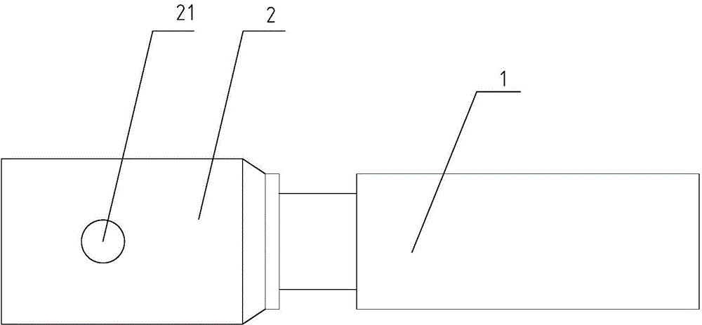
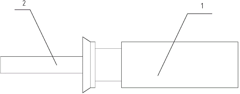
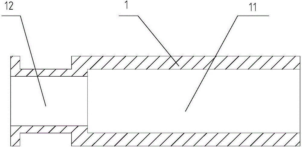
[0030] refer to figure 1 and figure 2 , a device clamp for a distribution line shown, including a connecting body, the side wall at one end of the connecting body is provided with a connecting hole 21, the end surface of the other end of the connecting body is provided with a receiving groove 11, and a fixing screw is connected to the connecting hole 21 , the fixing screw is connected to the equipment of the distribution line, and the power line of the distribution line is installed in the receiving groove 11. The connecting body can be compressed by the crimping pliers to shrink the receiving groove 11, and the inner wall of the receiving groove 11 is compressed and fixed to the internal power cord, so as to realize the conductive connection between the equipment and the power cord. The installation of the invention is simple and convenient, and the error of installation quality is reduced. The inner wall of the receiving groove 11 wraps the power line, which increases the...
Embodiment 2
[0034] refer to Figure 5 and in Example 1 figure 1 , shows a kind of equipment clamp for distribution lines, including a connecting body, the connecting body includes a connecting plate 2 and a sleeve 1, the surface of the connecting plate 2 is provided with a connecting hole 21, and one end of the sleeve 1 is provided with a receiving groove 11, and the sleeve The other end of the pipe 1 is connected to the connection plate 2, and the connection hole 21 is connected with a fixing screw, which is connected to the equipment of the power distribution line. The inner sleeve 3 is arranged in the accommodation groove 11 of the inner sleeve 3, and the inner sleeve 3 is arranged along the axial direction of the casing 1, and the power line of the distribution line is installed in the inner sleeve 3, and the inner circular surface of the inner sleeve 3 is arranged Notch 31, the outer circular surface of inner cover 3 is provided with groove 32, and the inner wall of accommodation gr...
Embodiment 3
[0037] refer to Image 6 and Example 1 figure 1 , shows a kind of equipment clamp for distribution lines, the connecting body includes a connecting plate 2 and a sleeve 1, the surface of the connecting plate 2 is provided with a connecting hole 21, one end of the sleeve 1 is provided with a receiving groove 11, and the other end of the sleeve 1 One end is connected with the connection plate 2, the connection hole 21 is connected with a fixing screw, the power cord is installed in the accommodation groove 11, and the side wall of the accommodation groove 11 is provided with a deformation groove 13, and the opposite surface of the accommodation groove 11 is provided with a threaded hole 131, and the thread A locking screw 42 is connected to the hole 131. Tighten the locking screw 42 so that the opposite surface of the deformation groove 13 approaches, the deformation groove 13 shrinks, the aperture of the accommodation groove 11 decreases, the accommodation groove 11 compresses ...
PUM
 Abstract
Description
Claims
Application Information
 - R&D
- Intellectual Property
- Life Sciences
- Materials
- Tech Scout
- Unparalleled Data Quality
- Higher Quality Content
- 60% Fewer Hallucinations
Browse by: Latest US Patents, China's latest patents, Technical Efficacy Thesaurus, Application Domain, Technology Topic, Popular Technical Reports.
© 2025 PatSnap. All rights reserved.Legal|Privacy policy|Modern Slavery Act Transparency Statement|Sitemap|About US| Contact US: help@patsnap.com


