
Calibration method and calibration circuit for charging control circuit

A charging control and calibration method technology, applied in electronic circuit testing, battery circuit devices, circuit devices, etc., can solve problems such as transistors being easily damaged, and achieve the effect of avoiding damage

Active Publication Date: 2015-06-03
SPREADTRUM COMM (SHANGHAI) CO LTD
View PDF4 Cites 4 Cited by
  • Summary
  • Abstract
  • Description
  • Claims
  • Application Information

AI Technical Summary

Problems solved by technology

[0014] The problem solved by the invention is that the transistors in the existing charging circuit are easily damaged

Method used


Image

  • Calibration method and calibration circuit for charging control circuit
  • Calibration method and calibration circuit for charging control circuit
  • Calibration method and calibration circuit for charging control circuit

Examples


Embodiment Construction

[0046] In order to make the above-mentioned objects, features and advantages of the present invention more obvious and understandable, the specific embodiments of the present invention will be described in detail below with reference to the accompanying drawings.

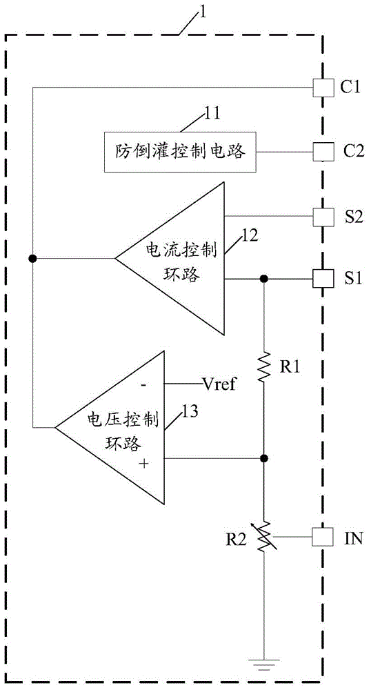
[0047] Continue to refer figure 2 The charging control circuit 1 involved in the embodiment of the present invention includes: a current and voltage control terminal C1, an anti-backflow control terminal C2, a voltage sampling terminal S1 and a current sampling terminal S2, a voltage regulation terminal IN, an anti-backflow control circuit 11, and a current control loop 12. Voltage control loop 13, first resistor R1 and second resistor R2.

[0048] The backflow prevention control circuit 11 is connected to the backflow prevention control terminal C2.

[0049] The first input terminal of the current control loop 12 is connected to the current sampling terminal S2, and the second input terminal of the current control loop 1...


PUM


Abstract

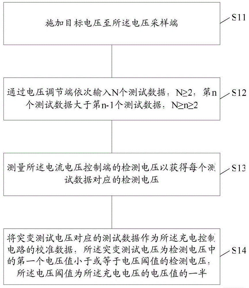
The invention provides a calibration method and a calibration circuit for a charging control circuit. The charging control circuit is applicable to the charging voltage input, and comprises a current voltage control end, a voltage regulating end and a voltage sampling end. The calibration method comprises the following steps that target voltage is exerted to the voltage sampling end; N test data is sequentially input through the voltage regulating end, the N is greater than or equal to 2, the n-th test data is greater than the (n-1)th test data, the n is smaller than or equal to the N but is greater than or equal to 2, and the detection voltage of the current and voltage control end is measured for obtaining the corresponding detection voltage of each test data; the test data corresponding to the mutation testing voltage is used as the calibration data of the charging control circuit, the mutation testing voltage is the first detection voltage with the voltage value being smaller than or equal to the voltage threshold in the detection voltage, and the voltage threshold is a half of the voltage value of the charging voltage.

Description

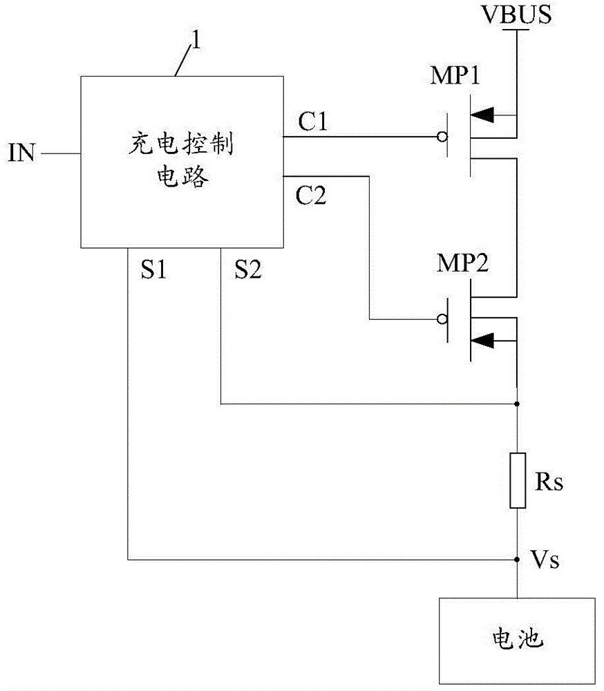
Technical field [0001] The invention relates to a calibration method and a calibration circuit of a charging control circuit. Background technique [0002] Modern electronic products are becoming more portable and intelligent, so their power supply batteries are required to be portable and efficient. Rechargeable batteries are rechargeable batteries with a limited number of recharges. They have the advantages of economy and environmental protection. Lithium-ion batteries are gradually becoming the standard batteries for modern electronic products due to their excellent performance. [0003] An electronic device is usually provided with a charging circuit to manage the charging between the adapter and the rechargeable battery. Such as figure 1 As shown, the existing charging circuit includes: a charging control circuit 1, a first PMOS transistor MP1, a second PMOS transistor MP2, and a sampling resistor Rs. [0004] The charging control circuit 1 includes a current and voltage contr...

Claims


Application Information

Patent Timeline
IPC IPC(8): H02J7/00G01R31/28
Inventor 张富强
Owner SPREADTRUM COMM (SHANGHAI) CO LTD
Learn More