Automated biplane-pw workflow for ultrasonic stenosis assessment

A dual-plane, ultrasonic diagnosis technology, applied in the field of medical diagnosis systems, which can solve problems such as incorrect peak velocity measurement, inaccurate angle correction, inconsistency, etc.

Active Publication Date: 2015-06-03
KONINKLJIJKE PHILIPS NV
View PDF6 Cites 4 Cited by
  • Summary
  • Abstract
  • Description
  • Claims
  • Application Information

AI Technical Summary

Problems solved by technology

Inaccurate angle corrections can lead to the possibility of incorrect peak velocity measurements,

Method used


Image

  • Automated biplane-pw workflow for ultrasonic stenosis assessment
  • Automated biplane-pw workflow for ultrasonic stenosis assessment
  • Automated biplane-pw workflow for ultrasonic stenosis assessment

Examples


Embodiment Construction

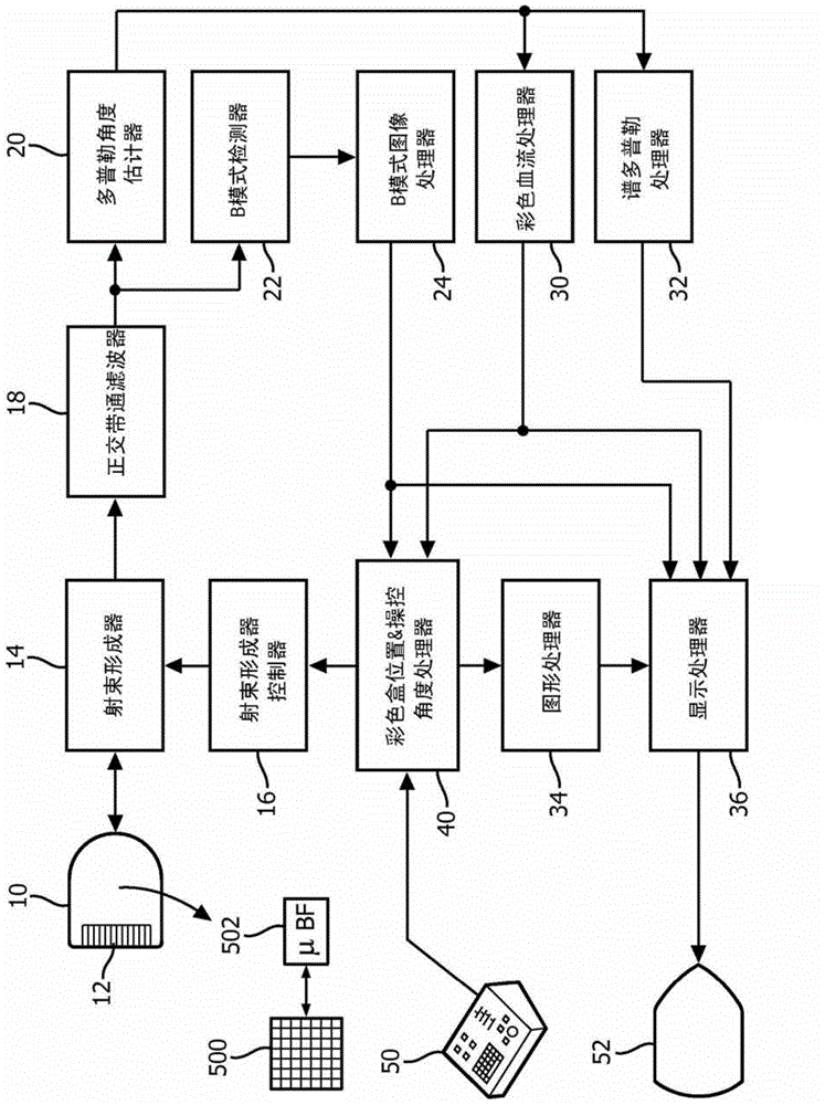
[0011] first reference figure 1 , shows in block diagram form an ultrasound system constructed in accordance with the principles of the present invention. The ultrasound probe 10 contains a transducer array 12 of transducer elements that transmit ultrasound waves into the body and receive returning echo signals. The emitted waves are directed into a beam or scanline to interrogate a region of interest in the body. One-dimensional arrays can be used to emit beams in a single plane for two-dimensional imaging. For the stenosis assessment examination according to the present invention, the probe 10 is a matrix array probe having a two-dimensional array of transducer elements 500 coupled to a probe microbeamformer 502 . Matrix array probes can be used to transmit beams over volumetric regions of the body for three-dimensional imaging. As explained more fully below, the beam can be steered and focused in different directions by the probe to interrogate tissue in a particular loc...


PUM


Abstract

An ultrasound system with a matrix array (500) probe (10) operable in the biplane mode is used to assess stenosis of a blood vessel by simultaneously displaying two color Doppler biplane images (60a, 60b) of the vessel, one a longitudinal cross-sectional view (60a) and the other a transverse cross-sectional view (60b). The two image planes intersect along a Doppler beam line (68) used for PW Doppler. A sample volume graphic (SV) is positioned over the blood vessel at the peak velocity location in one image, then positioned over the blood vessel at the peak velocity location in the other image. As the sample volume location is moved in one image, the plane and/or sample volume location of the other image is adjusted correspondingly. Spectral Doppler data (62) is then acquired and displayed from the sample volume location.

Description

technical field [0001] The present invention relates to medical diagnostic systems, and in particular to diagnostic ultrasound systems for assessing blood flow through narrow blood vessels or at other points in the cardiovascular system. Background technique [0002] An important procedure in many standard vascular ultrasonography is to obtain an assessment of arterial narrowing or constriction. This is usually assessed using color Doppler to find the stenosis and PW-Doppler to measure peak flow velocity, which correlates to the degree of stenosis. Although this is a well-established workflow for assessing vessel stenosis, it suffers from a number of limitations well known to clinical users. First, there are many manual steps involved that require an experienced user in order to perform them successfully, and can also require a significant amount of time. Additionally, since the user can only visualize vascular blood flow in a two-dimensional (2D) image plane with the aid ...

Claims


Application Information

Patent Timeline
IPC IPC(8): A61B8/08A61B8/06G01S15/89A61B8/14
CPCA61B8/488A61B5/02A61B8/06A61B8/145A61B8/483A61B8/5223G01S7/52063G01S7/52066G01S7/52073G01S7/52074G01S7/5208G01S15/8915G01S15/8925G01S15/8979G01S15/8988G01S15/8993G06T7/0012
Inventor J·R·杰戈K·W·约翰逊A·萨阿德D·A·赫尔
Owner KONINKLJIJKE PHILIPS NV
Why Eureka
Try Eureka