Novel universal medical infusion head with automatic infusion bottle changing function

A general-purpose, infusion head technology, applied in the direction of the device introduced into the body, etc., can solve the problems of inability to use a soft bag container for infusion, affecting the outflow of liquid, and preventing the liquid from flowing out. The principle and path are clear, convenient for processing and production, The effect of increasing buoyancy

Inactive Publication Date: 2015-06-10
刘玮
View PDF6 Cites 1 Cited by
  • Summary
  • Abstract
  • Description
  • Claims
  • Application Information

AI Technical Summary

Problems solved by technology

[0003] Invention patent ZL2012104089744 "A dual-channel infusion head for automatic control of liquid and gas time-sharing input". Air intake, start infusion as long as it is connected
Because such a synchronous valve design will cause the air entering the previous valve chamber to enter the latter valve chamber through the movement groove at the bottom of the valve chamber interval, and produce two consequences. One is that the gas entering the latter valve chamber may directly enter the outlet liquid Second, even if the gas does not flow into the liquid outlet pipe but flows to the pipe opening at the top of the valve chamber, this will also affect the outflow of the liquid in the bottle at the opening, because the air pressure at the top openings of the front and rear valve chambers is equal , the liquid does not come out
[0006] To sum up, the previous generation of

Method used


Image

  • Novel universal medical infusion head with automatic infusion bottle changing function
  • Novel universal medical infusion head with automatic infusion bottle changing function
  • Novel universal medical infusion head with automatic infusion bottle changing function

Examples


Example Embodiment

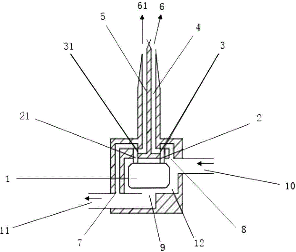
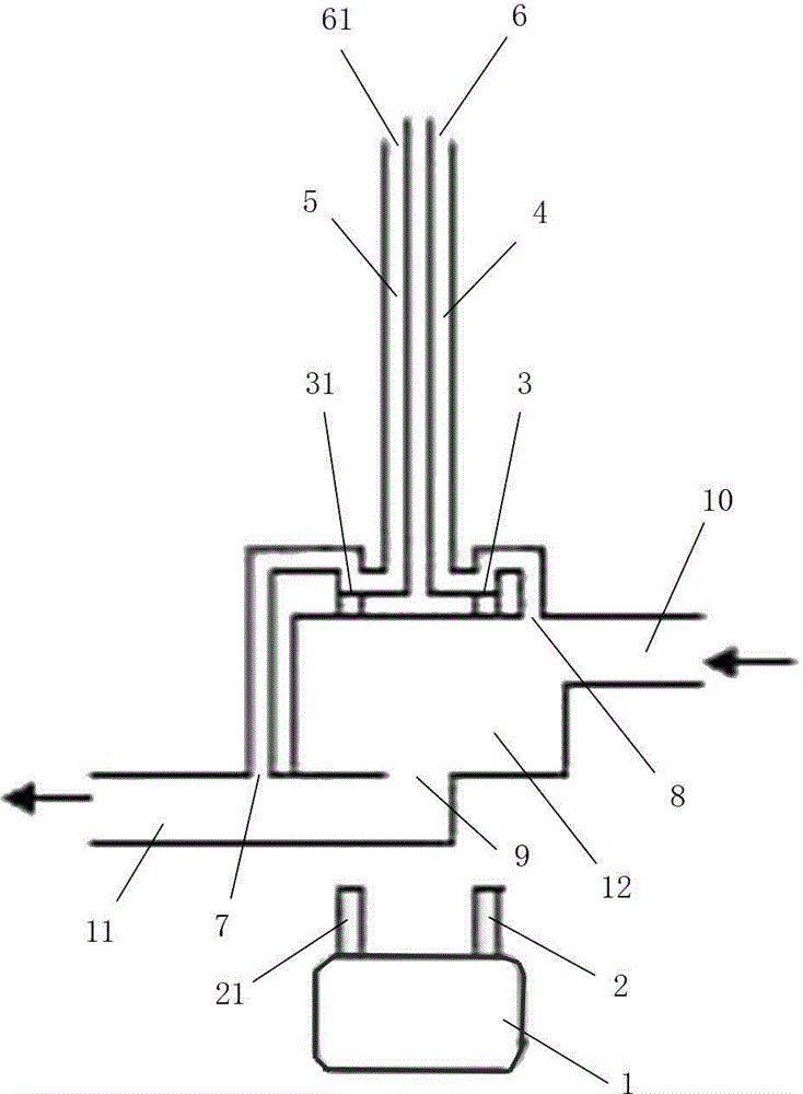
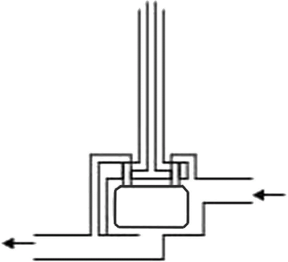
[0021] In order to facilitate the understanding of the present invention, the present invention will be described more fully below with reference to the relevant drawings. The preferred embodiment of the invention is shown in the drawings. However, the present invention can be implemented in many different forms and is not limited to the embodiments described herein. On the contrary, the purpose of providing these embodiments is to make the disclosure of the present invention more thorough and comprehensive.

[0022] It should be noted that when an element is considered to be "disposed" on another element, it may be directly disposed or connected to another element, or there may be a central element at the same time. Hard bottle infusion or soft bottle infusion means that the current infusion head is inserted into the hard or soft bottle and the infusion is performed.

[0023] Unless otherwise defined, all technical and scientific terms used herein have the same meaning as common...


PUM


Abstract

The invention relates to a novel universal medical infusion head with an automatic infusion bottle changing function. The infusion head comprises an infusion head body, two passages arranged on the infusion head body, a floater valve chamber, a liquid inlet tube and a liquid outlet tube, wherein the two passages are an air-liquid passage and a liquid passage, the top ends of the two passages are communicated into a bottle or bag, and a valve is disposed on each passage; the bottom-end opening of the air-liquid passage is formed in the top of the floater valve chamber, and the bottom-end opening of the liquid passage is formed in the liquid outlet tube; a floater with two valve rods at the top is disposed in the floater valve chamber, and a liquid outlet communicated with the liquid outlet tube is formed in the bottom of the floater valve chamber; the two valve rods on the floater respectively correspond to the valves on the two passages, and the bottom end of the floater faces directly to the liquid outlet. The novel universal medical infusion head has the advantages that the two valves are driven by one floater, and the two valves of two valve chambers are opened and closed synchronously; by the three openings of the valve chambers, floater valve movements and a liquid passage directly communicating to the liquid outlet tube, suction force in the tube is fully utilized, and pulse infusion is achieved.

Description

technical field [0001] The invention relates to an infusion device used in the medical industry, in particular to a new general-purpose medical infusion automatic liquid infusion head which can automatically change bottles and continue liquid when multiple soft bottles, multiple hard bottles or multiple soft and hard bottles are mixed infusion. . Background technique [0002] In the medical industry, continuous infusion is not common. The traditional single-bottle infusion and manual bottle replacement bring great labor intensity to medical workers, and it is easy to cause some medical accidents due to inadvertent negligence. In order to solve the above problems and realize the purpose of automatic bottle change for continuous infusion, the inventors of the present application have developed several generations of products that can realize automatic liquid succession. [0003] Invention patent ZL2012104089744 "A dual-channel infusion head for automatic control of liquid and...

Claims


Application Information

Patent Timeline
IPC IPC(8): A61M5/14
CPCA61M5/162A61M2005/1623
Inventor 刘玮沈颖惠刘诗舫沈博宇刘绍勇
Owner 刘玮
Why Eureka
Try Eureka