Material receiving device for punch press

A material receiving device and punching technology, applied in the field of mechanical processing, can solve the problems of poor production safety and high labor intensity of workers, and achieve the effects of convenient operation, easy processing and manufacturing, and simple overall structure design.

Inactive Publication Date: 2015-06-10
SUZHOU CMT AUTOMATION EQUIP
View PDF8 Cites 1 Cited by
  • Summary
  • Abstract
  • Description
  • Claims
  • Application Information

AI Technical Summary

Problems solved by technology

[0003] The technical problem to be solved by the present invention is: how to solve the problems of high labor intensity and poor production safety when the existing machine tool is processing the motor stator and rotor

Method used


Image

  • Material receiving device for punch press
  • Material receiving device for punch press

Examples


Embodiment Construction

[0013] The specific implementation manners of the present invention will be further described in detail below in conjunction with the accompanying drawings and embodiments. The following examples are used to illustrate the present invention, but are not intended to limit the scope of the present invention.

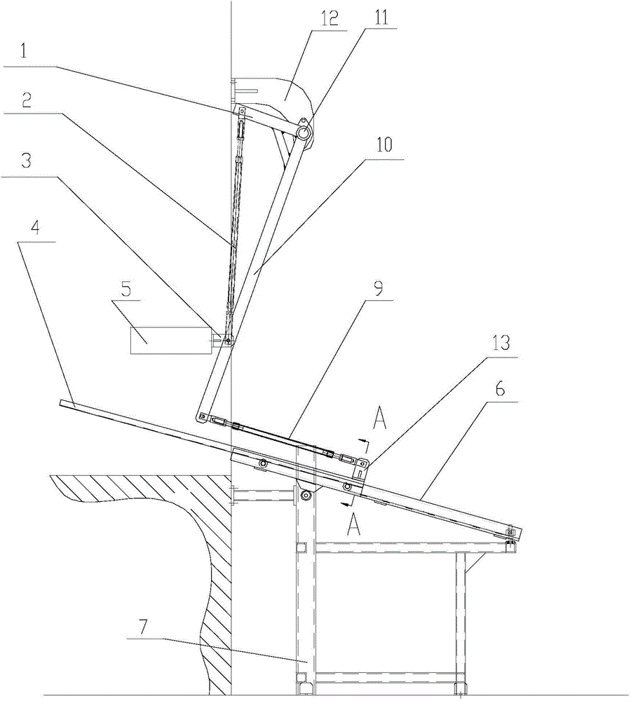
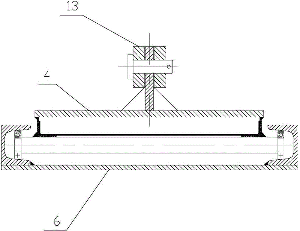
[0014] Such as Figure 1 to Figure 2 The shown punch receiving device of the present invention includes: a base 7, a transmission unit and a receiving unit; the receiving unit includes a receiving bracket 6 and a movable receiving plate 8, and the receiving bracket 6 is fixed on the base 7, and the receiving unit is movable. The material plate 8 is flexibly connected with the receiving support 6, and can slide back and forth on the receiving support 6. Movable material receiving plate 8 is used for reclaiming the motor sub-machine machined. The direction of the receiving support 6 can be set according to actual needs, and the angle with the working plane of the machine t...


PUM


Abstract

The invention discloses a material receiving device for a punch press. The material receiving device comprises a base, a transmission unit and a material collecting unit, wherein the material collecting unit comprises a material collecting bracket and a movable material receiving plate; the transmission unit comprises an upper fixed bracket, a lower fixed bracket, a middle supporting seat, a short connecting rod, a long connecting rod, an upper adjustment connecting rod and a lower adjustment connecting rod. The punch press is properly improved by the material receiving device, automatic material receiving and punching can be carried out simultaneously, so that the whole production process is more effective, more convenient and safer.

Description

technical field [0001] The invention relates to the technical field of mechanical processing, in particular to a material receiving device for a punch press. Background technique [0002] In the past, the stator and rotor punches of various types of motors were generally processed on the corresponding punching machines. Usually, the operator of the punching machine took out the punched motor stator and rotor punches with special magnetic sheets, and then stacked them neatly according to requirements. Since this work depends purely on the proficiency of the operator, coupled with the particularity of the work and frequent reciprocating work, the labor intensity of the operator is very high, and it is easy to cause fatigue, and the work efficiency is low, which also brings serious safety hazards to safe production. Contents of the invention [0003] The technical problem to be solved by the present invention is: how to solve the problems of high labor intensity and poor prod...

Claims


Application Information

Patent Timeline
Patent Type & Authority Applications(China)
IPC IPC(8): B21D43/20
CPCB21D43/22
Inventor 张永兵
Owner SUZHOU CMT AUTOMATION EQUIP
Why Eureka
Try Eureka