Automatic foam cutter

A cutting machine and foam technology, applied in metal processing and other directions, can solve the problems of large working space, low cutting accuracy, troublesome installation of fixed heating wires, etc. Effect

Inactive Publication Date: 2015-06-10
SHENZHEN YIDAO CHUANGMENG DESIGN TECH
View PDF5 Cites 12 Cited by
  • Summary
  • Abstract
  • Description
  • Claims
  • Application Information

AI Technical Summary

Problems solved by technology

[0008] 1. It is troublesome to install and fix the heating wire, and it is inconvenient to adjust the tension of the heating wire;
[0009] 2. The stability of the heating wire is not enough, and the cutting accuracy is low;
[0010]

Method used


Image

  • Automatic foam cutter
  • Automatic foam cutter
  • Automatic foam cutter

Examples


Embodiment 1

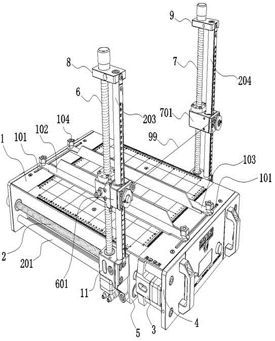
[0036] according to figure 1 As shown, the automatic foam cutting machine in the present invention includes a control host 1, and the control host 1 has a data input port, a memory, a processor and a controller that sequentially form a data connection.

[0037] The front part and the rear part of the top surface of the housing of the control host 1 are respectively provided with a sliding slot 101 parallel to each other, and a foam clamping device is mounted on the sliding slot 101 . Preferably, the foam clamping device is composed of a first L-shaped clamping plate 102 , a second L-shaped clamping plate 103 , and cap bolts 104 respectively arranged at both ends of the first L-shaped clamping plate 102 and the second L-shaped clamping plate 103 . Cap bolts 104 at both ends of the first L-shaped clamping plate 102 and the second L-shaped clamping plate 103 are respectively fitted in the slide grooves 101 .

[0038] A first horizontal lead screw 2 and a second horizontal lead s...

Embodiment 2

[0052] according to Figure 6 As shown, due to the limitation of the structure of the ball screw pair, each slider may rotate on the screw with the axis of the screw as the central axis during actual use, and the rotating slider will affect the foam cutting effect. In order to make each ball slider run on the lead screw in a stable posture, this embodiment is an improvement on the basis of the first embodiment:

[0053] It also includes a first circular rail 201 and a second circular rail arranged in parallel with the first horizontal lead screw 2 and the second horizontal lead screw respectively, and is spaced in parallel with the first vertical lead screw 6 and the second vertical lead screw 7 respectively. Set the third circular track and the fourth circular track.

[0054] The first circular rail 201, the second circular rail, the third circular rail 203 and the fourth circular rail 204 are respectively covered with a first linear bearing 202, a second linear bearing, a t...

Embodiment 3

[0056] In order to make the vertical lead screw of the foam cutting machine foldable and folded for convenient transportation or storage, this embodiment is an improvement on the basis of any of the above-mentioned embodiments:

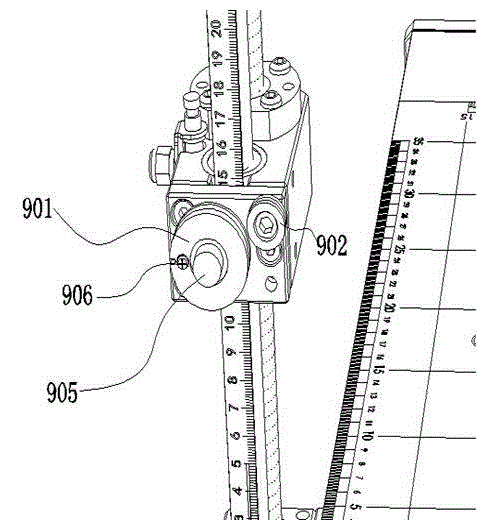
[0057] according to Figure 7 and Figure 8 As shown, it includes a first slider connecting block 11 and a second slider connecting block that can be disassembled to the first horizontal ball slider 5 and the second horizontal ball slider respectively. Wherein, the bottom end of the first vertical lead screw 6 and the third servo motor that forms a transmission connection with it are arranged in the first slider connecting block 11, and the bottom end of the second vertical lead screw 7 and the third servo motor that forms a transmission connection with it Four servo motors are arranged in the second slider connecting block.

[0058] A first threaded connection hole 503 and a second threaded connection hole 504 located on the upper part of the first...


PUM


Abstract

The invention relates to an automatic foam cutter. The automatic foam cutter comprises a control host, a horizontal screw and a vertical screw, wherein a first vertical ball sliding block and a second vertical ball sliding block are arranged on the vertical screw respectively; an electric heating wire is connected between the first vertical ball sliding block and the second vertical ball sliding block. According to the existing cutting information such as a CAD file, the foam cutter controls servo motors, so that the screws rotate at special rotation speed and rotation direction to drive the ball sliding blocks to move, and the electric heating wire is driven to carry out three-dimensional cutting on the foam according to the motion synthesis of the ball sliding blocks. The foam cutter is high in cutting efficiency, high in safety, high in processing accuracy and high in automation degree.

Description

technical field [0001] The invention relates to a foam cutting machine, in particular to a foam cutting machine with a high degree of automation, which is mainly used in the fields of making high-precision foam models and foam handicrafts. Background technique [0002] At present, the more commonly used foam cutting method is to use a heated electric heating wire to cut the foam. The cutting machine has a large industrial foam cutting machine and a small manual foam cutting machine. [0003] Large foam cutting machines for industrial use are bulky and designed separately. The installation is not only limited by the site area, but also needs to be transported to the site for assembly and debugging of various independent parts during installation, which is very troublesome. [0004] Traditional small manual foam cutting machines generally use manual operation to push the foam to the heating wire. This method of operation is prone to accidents, low safety, low production effici...

Claims


Application Information

Patent Timeline
IPC IPC(8): B26F3/12B26D7/08B26D5/08B26D7/26
Inventor 凌慧
Owner SHENZHEN YIDAO CHUANGMENG DESIGN TECH
Why Eureka
Try Eureka