
Trash-cleaning ship structure

A cleaning and cleaning technology, applied in the field of cleaning and cleaning ship structures, can solve problems such as pollution in urban sea areas

Inactive Publication Date: 2015-06-10
王楠
View PDF0 Cites 0 Cited by
  • Summary
  • Abstract
  • Description
  • Claims
  • Application Information

AI Technical Summary

Problems solved by technology

[0002] At present, the sea area of ​​coastal cities is seriously polluted, and there are a large amount of domestic garbage floating in the seawater. There is no special boat for marine cleaning and cleaning on the market.

Method used


Image

  • Trash-cleaning ship structure

Examples


Embodiment 1

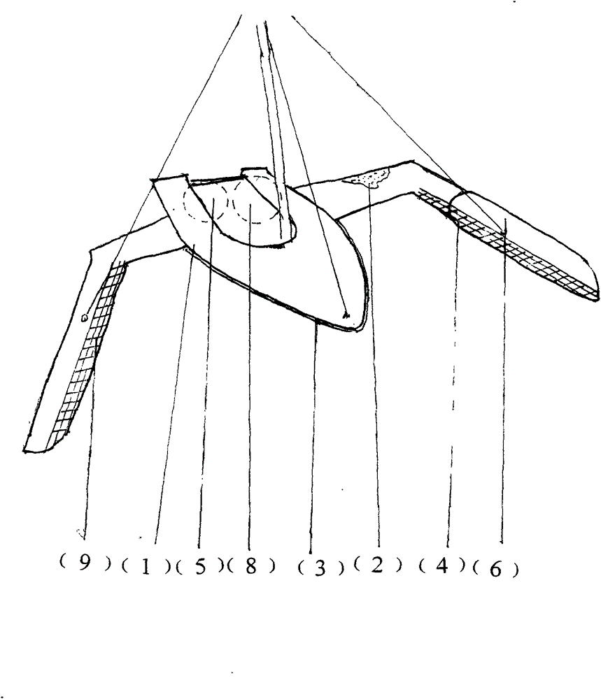
[0006] Embodiment 1, a cleaning and cleaning ship structure includes: hull shell (1), the hull shell is made of stainless steel plate (1) welded, internal pressure-soluble polyvinyl chloride insulation material (2), a The structural shell of the cleaning and cleaning ship is provided with anti-collision rubber rings (3), and a rubber sealing layer (4) is provided in the body of a cleaning and cleaning ship. A dirt-cleaning filter screen (9) is arranged below, and the mesh surface layer is coated with a waterproof sealant (4), and a garbage sorter (5) and a garbage packaging bag (8) are arranged in the ship.


PUM


Abstract

A trash-cleaning ship structure has various advantages. The trash-cleaning ship structure uses a ship shell formed by welding a stainless steel plate, wherein a polyvinyl chloride insulation material is formed inside the ship shell through pressure solution; the shell of the trash-cleaning ship structure is provided with an anti-collision rubber ring; a sealing rubber layer is arranged inside the trash-cleaning ship body; left and right crab claw-type trash-cleaning pliers are arranged on the ship shell; trash-cleaning filter screens are arranged beneath the pliers; the surfaces of the trash-cleaning filter screens are coated with water-proof sealing rubber; a trash sorter and a trash packaging bag are arranged inside the trash-cleaning ship structure. The trash-cleaning ship structure can be operated through remote control.

Description

1. Technical field: [0001] The invention relates to a structure of a pollution cleaning ship, which belongs to the field of new environmental protection products. 2. Background technology: [0002] At present, the waters of coastal cities are seriously polluted, and there are a large amount of domestic garbage floating in the seawater. There are no ships specially used for marine cleaning and cleaning on the market. 3. Contents of the invention: [0003] Aiming at the deficiencies in the prior art, the present invention proposes a structure of a cleaning and cleaning ship, which has all the advantages, and is characterized in that: a structure of a cleaning and cleaning ship is welded by stainless steel plates (1), a The structure of the cleaning and cleaning ship includes: the shell of the hull (1), the shell of the hull is welded by stainless steel plates (1), and the internal pressure-soluble polyvinyl chloride insulation material (2), a structural shell of the cleaning...

Claims


Application Information

Patent Timeline
IPC IPC(8): B63B35/32
Inventor 王楠
Owner 王楠
Learn More